
Method for predicating line loss rate of power grid

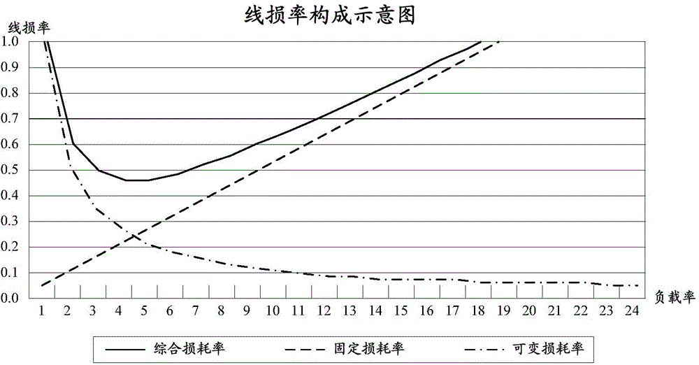
A power grid line and power grid technology, applied in the direction of measuring electricity, measuring electrical variables, measuring resistance/reactance/impedance, etc., can solve problems such as difficult to obtain calculation accuracy, large complexity, ambiguity and one-sidedness, and achieve simple and fast calculation process , the effect of high calculation accuracy

Inactive Publication Date: 2015-05-20
HEBI POWER SUPPLY OF HENAN ELECTRIC POWERCORP
View PDF6 Cites 14 Cited by
  • Summary
  • Abstract
  • Description
  • Claims
  • Application Information

AI Technical Summary

Problems solved by technology

[0006] 2) The fixed loss of the component and its loss rate
[0019] (2) Variable loss and variable loss rate
[0035] 2) Transformer variable loss and variable loss rate
[0048] But without exception, there are great complexity, ambiguity and one-sidedness in the calculation of the line loss rate in the above methods, and it is difficult to obtain good calculation accuracy in practice

Method used


Image

  • Method for predicating line loss rate of power grid
  • Method for predicating line loss rate of power grid
  • Method for predicating line loss rate of power grid

Examples


Embodiment 1

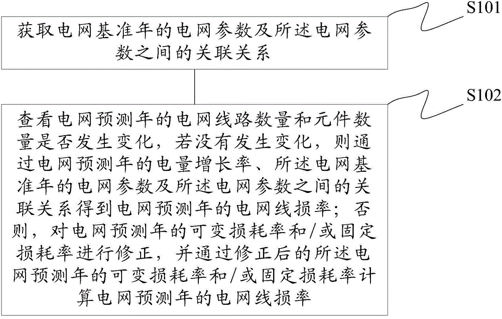
[0100] This embodiment provides a method for predicting the power grid line loss rate, such as figure 2 As shown, the method described in this embodiment includes the following steps:

[0101] Step S101: Obtain the grid parameters of the grid base year and the relationship between the grid parameters;

[0102] The grid reference year refers to the year in which the actual grid parameters can be obtained, usually one or two years before the grid forecast year; the grid forecast year is one or several years after the current year, and the current year is usually used as the grid benchmark year, and the next year or next few years will be the power grid forecast year. The grid parameters of the grid base year are selected from the actual grid data, which can ensure the accuracy and pertinence of the subsequent prediction of the grid line loss rate.

[0103] Step S102: Check whether the number of grid lines and the number of components in the forecast year of the grid have change...

Embodiment 2

[0150] This embodiment describes the present invention in detail through an actual scene.

[0151] Step S201: Obtain the grid parameters in the base year of the grid and the relationship between the grid parameters;

[0152] Taking a city-level power grid with a voltage level of 220kV and below as an example, the process of predicting the line loss rate based on the voltage division line loss rate and the voltage division power growth rate is explained.

[0153] Table 1 is the data code of the sub-voltage line loss rate table in the base year, and the relationship between the data is detailed in the table below.

[0154] Table 1

[0155]

[0156] In the above table, there are 5 levels of grid voltage in this area ranging from 220kV to 0.4kV, and the levels are represented by 1, 2, 3, 4, and 5 respectively. The voltage level of grids in other areas depends on the actual situation; (The power supply at the head end of the line) is expressed, the transferred power is represe...


PUM


Abstract

The invention provides a method for predicating a line loss rate of a power grid. The method comprises the following steps: obtaining power grid parameters in a power grid reference year and incidence relation among the power grid parameters; reviewing whether the quantity of power grid lines and the quantity of components in a power grid predicating year are changed or not; if so, obtaining the line loss rate of the power grid in the power grid predicating year according to the growth rate of electric quantity in the power grid predicating year, the power grid parameters in the power grid reference year and the incidence relation among the power grid parameters; otherwise, modifying a variable loss rate and / or a constant loss rate in the power grid predicating year, and calculating the line loss rate of the power grid in the power grid predicating year according to the modified variable loss rate and / or constant loss rate in the power grid predicating year.

Description

technical field [0001] The invention relates to the technical field of power grid control, in particular to a method for predicting the line loss rate of a power grid. Background technique [0002] The line loss rate of the power grid is the ratio of line loss power to power supply. According to the calculation principle of line loss theory, line loss includes fixed loss and variable loss. Correspondingly, the line loss rate is also composed of a fixed loss rate and a variable loss rate. Specifically include: [0003] (1) Fixed loss and fixed loss rate [0004] 1) The fixed loss of the line and its loss rate [0005] For the fixed loss of the line, it usually refers to the corona and conductance loss of the line, which is related to the voltage level and the length of the line. Generally, it can be approximated by the ratio of fixed loss to variable loss. For example, according to "Rural Power Grid Power Saving Technology Regulations (DL / T738—2000)” stipulates in the rec...

Claims


Application Information

Patent Timeline
Patent Type & Authority Applications(China)
IPC IPC(8): G01R31/00G01R27/26
Inventor 牛迎水白江红冯义吕志民赵民亚
Owner HEBI POWER SUPPLY OF HENAN ELECTRIC POWERCORP
Learn More