
A suction cup for absorbing silicon wafers

A suction cup and silicon chip technology, which is applied in the manufacture of electrical components, circuits, semiconductors/solid-state devices, etc., can solve the problems of silicon chip damage at the center of the silicon chip, local impact of the silicon chip, etc., and achieve the effect of avoiding damage

Active Publication Date: 2018-12-07
SHENYANG SIASUN ROBOT & AUTOMATION
View PDF6 Cites 0 Cited by
  • Summary
  • Abstract
  • Description
  • Claims
  • Application Information

AI Technical Summary

Problems solved by technology

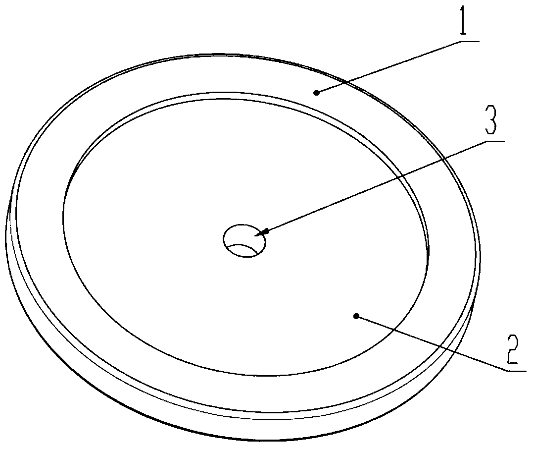
[0004] The current common suction cup is due to the suction hole in the center of the suction cup (such as figure 1 shown), at the moment of vacuum pumping and gas filling, the gas will cause a large local impact on the silicon wafer
And in order to obtain sufficient adsorption force, the contact area between the suction cup and the silicon wafer is often reduced, so that the formed vacuum adsorption chamber is concentrated at the center of the suction cup, which will cause excessive force on the center of the silicon wafer and cause damage to the silicon wafer.

Method used


Image

  • A suction cup for absorbing silicon wafers
  • A suction cup for absorbing silicon wafers
  • A suction cup for absorbing silicon wafers

Examples


Embodiment Construction

[0023] The present invention will be described in further detail below in conjunction with the drawings and specific embodiments, and it should be understood that the drawings and embodiments are only exemplary rather than limiting the present invention.

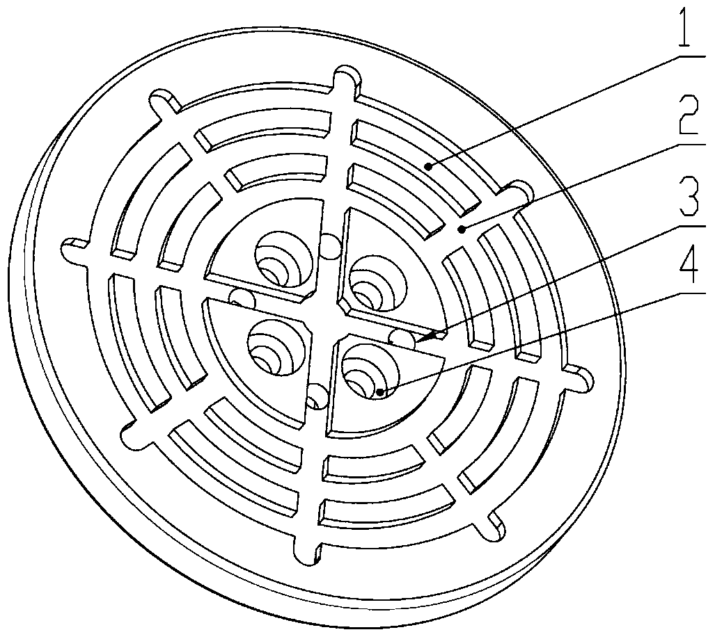
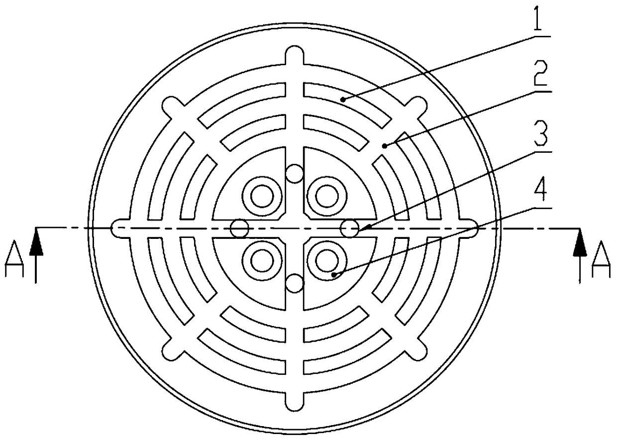
[0024] refer to Figure 2 to Figure 6 , is a schematic diagram showing the structure of a suction cup for absorbing a silicon wafer according to a preferred embodiment of the present invention.

[0025] According to the suction cup used for absorbing silicon wafers, it includes an upper part in contact with the silicon wafer and a lower part opposite to the upper part, and the upper part is provided with a support surface 1 , a vacuum suction chamber 2 , and an air suction hole 3 . The supporting surface 1 is used to support the silicon wafer on the adsorption; the air pumping hole 3 communicates with the vacuum adsorption chamber 2 and is used for evacuating and forming a vacuum in the vacuum adsorption chamber 2 .

[0026...


PUM


Abstract

The invention relates to the technical field of silicon wafer transmission and particularly discloses a sucker used for sucking silicon wafers. The sucker comprises an upper portion in contact with the silicon wafers and a lower portion opposite to the upper portion, and the upper portion is provided with a supporting surface and vacuum sucking cavities. The sucker is characterized in that at least two extraction holes are arranged in the upper portion of the sucker. The extraction holes are arranged dispersedly by improvement of the sucker structure, so that local impact on the silicon wafers due to gas at the moment of vacuum extraction and gas filling is lowered; the patterns of the sucker are changed, and the vacuum sucking cavities are evenly disposed in the sucker in the radius direction evenly, so that the silicon wafers are avoided being damaged due to over-large local stress.

Description

technical field [0001] The invention relates to the technical field of silicon wafer transmission, in particular to a suction cup for absorbing silicon wafers. Background technique [0002] There are usually two ways to fix silicon wafers in the field of silicon wafer transportation, edge clamping and vacuum adsorption. Edge clamping refers to the use of clamping mechanism to clamp the edge of the silicon wafer. The edge clamping has little pollution to the bottom of the silicon wafer, but the structure is complicated, and the clamping force is difficult to guarantee, and when the silicon wafer needs to be rotated, it will be greatly increased. The overall moment of inertia places a burden on the drive system. [0003] Vacuum adsorption refers to using a suction cup to support the center of the silicon wafer and using vacuum to absorb the silicon wafer. The vacuum adsorption mechanism is relatively simple, but it will cause pollution to the bottom of the silicon wafer. In...

Claims


Application Information

Patent Timeline
Patent Type & Authority Patents(China)
IPC IPC(8): H01L21/683
CPCH01L21/6838
Inventor 张鹏李学威徐方曲征辉张一博何伟全
Owner SHENYANG SIASUN ROBOT & AUTOMATION
Learn More