A welding structure of lithium battery pole piece foil and tab

A welding structure and lithium battery technology, applied in structural parts, welding equipment, non-electric welding equipment, etc., can solve the problems of reduced connection strength between battery tabs and nickel strips, unsuitable for battery foils and tabs, etc., to improve The effect of service life, preventing shattering, and increasing connection strength

Active Publication Date: 2017-05-17
WANXIANG 123 CO LTD
View PDF4 Cites 1 Cited by
  • Summary
  • Abstract
  • Description
  • Claims
  • Application Information

AI Technical Summary

Problems solved by technology

This welding structure reduces the connection strength between the battery tab and the nickel strip, and is not suitable for the connection between the battery foil and the tab

Method used


Image

  • A welding structure of lithium battery pole piece foil and tab
  • A welding structure of lithium battery pole piece foil and tab
  • A welding structure of lithium battery pole piece foil and tab

Examples


Embodiment 1

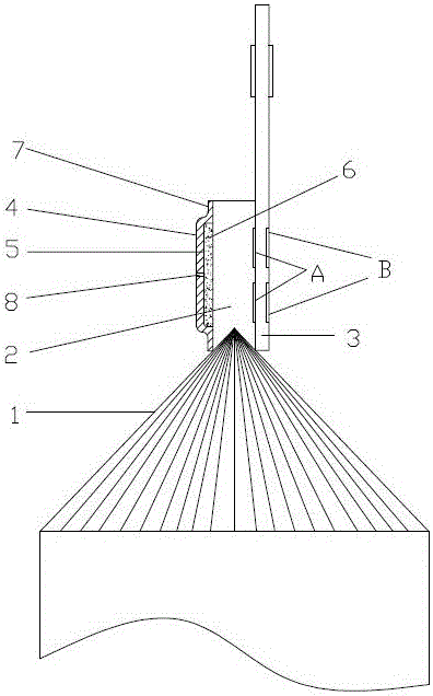
[0023] Embodiment 1: as figure 1 The welding structure of a lithium battery pole piece foil and tab is shown, including an electrode 2 formed by stacking a number of pole piece foils 1 together. The electrodes include a positive electrode and a negative electrode, and the pole piece foils 1 are welded together. connection, the right side of the electrode 2 is welded with a tab 3, the upper end of the tab is provided with a tab glue, the other side of the electrode 2 is provided with a shock absorber 4, and the inner side of the shock absorber 4 is provided with a shock absorber cavity 5, which absorbs The shock cavity is filled with high temperature resistant glue 6, and the periphery of the shock absorber 4 extends outward to form an annular welding surface 7. The annular welding surface has a back-shaped structure, and the welding connection between the annular welding surface 7 and the electrode 2 is welded. The bottom is provided with a through hole 8 . First, the shock a...

Embodiment 2

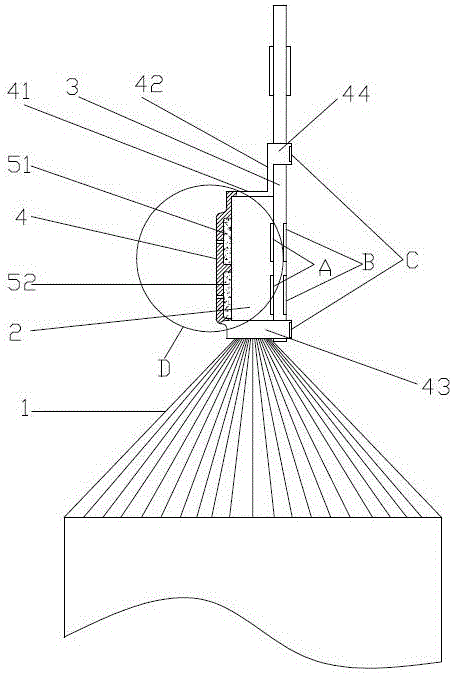
[0024] Embodiment 2: as figure 2 The welding structure of a lithium battery pole piece foil and tab is shown, including an electrode 2 formed by stacking a number of pole piece foils 1 together. The electrodes include a positive electrode and a negative electrode, and the pole piece foils 1 are welded together. connection, the right side of the electrode 2 is welded with a tab 3, the upper end of the tab is provided with a tab glue, the other side of the electrode 2 is provided with a shock absorber 4, and the inner side of the shock absorber 4 is provided with a shock absorber cavity 5, which absorbs The shock cavity is filled with high temperature resistant glue 6, and the periphery of the shock absorber 4 extends outwards to form an annular welding surface 7, which is in a back-shaped structure, and the welding connection between the annular welding surface 7 and the electrode 2, such as Figure 4 As shown, the shock absorbing chamber 5 is provided with spacers 9, and the ...


PUM

PropertyMeasurementUnit
thicknessaaaaaaaaaa

Abstract

The invention discloses a welding structure of a lithium battery pole piece foil and a pole ear, including an electrode formed by stacking a plurality of pole piece foils, the electrodes include a positive electrode and a negative electrode, and the pole piece foils are welded and connected One side of the electrode is welded with tabs, the other side of the electrode is provided with a shock absorber, the inner side of the shock absorber is provided with a shock absorber cavity, the shock absorber cavity is filled with high temperature resistant glue, and the periphery of the shock absorber extends outward A ring-shaped welding surface is formed, and the welding connection between the ring-shaped welding surface and the electrode is formed; a through hole is provided at the bottom of the shock-absorbing cavity; The baffle is attached to the outer end surface of the electrode, and the tab connecting piece is welded to the inner surface of the tab. Therefore, the present invention has the beneficial effect of improving the service life of the lithium battery by preventing the outermost pole piece foil from being crushed by ultrasonic waves when the pole piece foil is welded to the tab.

Description

technical field [0001] The invention relates to the technical field of connecting lithium battery pole pieces and foils, in particular to a welding structure between lithium battery pole pieces and tabs. Background technique [0002] The pole piece foil is drawn from one end of each lithium battery pole piece. After being drawn out, the pole piece foil on each pole piece is laminated and welded together to form a conductive end, and then connected to the tab, and then connected to the stage column. At present, the tab welding method of laminated soft-packed lithium batteries generally uses ultrasonic welding to pre-weld the leading foils between the pole pieces to form a pre-welded foil, and then ultrasonically welds the tab metal with the pre-welded foil. The welding foils are welded together to achieve the purpose of welding. However, in the process of ultrasonic welding, since the thickness of the foil drawn from the pole piece is very small, generally around 0.02mm, the...

Claims


Application Information

Patent Timeline
Patent Type & Authority Patents(China)
IPC IPC(8): H01M2/26H01M50/533H01M50/536
CPCB23K20/10H01M50/531Y02E60/10
Inventor 李凡群苏文俊谭歌朱修锋高新宝陈军
Owner WANXIANG 123 CO LTD
Why Eureka
Try Eureka