Steel-clad movable-type switch cabinet

A switchgear, removable technology, applied in the direction of substation/switchgear board/panel/desk, substation/distribution device enclosure, busbar/circuit layout, etc., can solve the problem of increasing complexity and reducing contact box to mutual inductance The safety distance between the branch busbar and the side plate of the device, and the increase of the production cost, etc., can achieve the effects of improving convenience and reliability, optimizing the secondary wiring device, and reducing the labor intensity of assembly.

Active Publication Date: 2015-05-20
ANHUI ZHONGDIAN XINGFA & XINLONG TECH CO LTD
View PDF4 Cites 2 Cited by
  • Summary
  • Abstract
  • Description
  • Claims
  • Application Information

AI Technical Summary

Problems solved by technology

The above two parts are usually distributed and assembled relatively independently, resulting in a large number of sheet metal parts constituting the device, and some sheet metal parts need to be bent many times, which not only brings a certain amount of tasks to the production assembly, but also improves the Cost of production
At the same time, since the secondary routing device is designed to be installed in the middle of the rear side panel, this will greatly reduce the safety distance from the contact box to the transformer branch busbar to the side panel, resulting in a tight safety distance here
When the specification of the branch busbar is too large, the safety distance here can no longer be satisfied. At this time, the secondary wiring device must be made of insulating material, so that this design not only increases the complexity of the design, but also increases the complexity of the design when using insulating material. , but also greatly increased the production cost

Method used


Image

  • Steel-clad movable-type switch cabinet
  • Steel-clad movable-type switch cabinet

Examples


Embodiment Construction

[0016] Below with reference to the accompanying drawings, through the description of the embodiments, the specific embodiments of the present invention, such as the shape, structure, mutual position and connection relationship between the various parts, the role and working principle of the various parts, etc., will be further described. Detailed instructions:

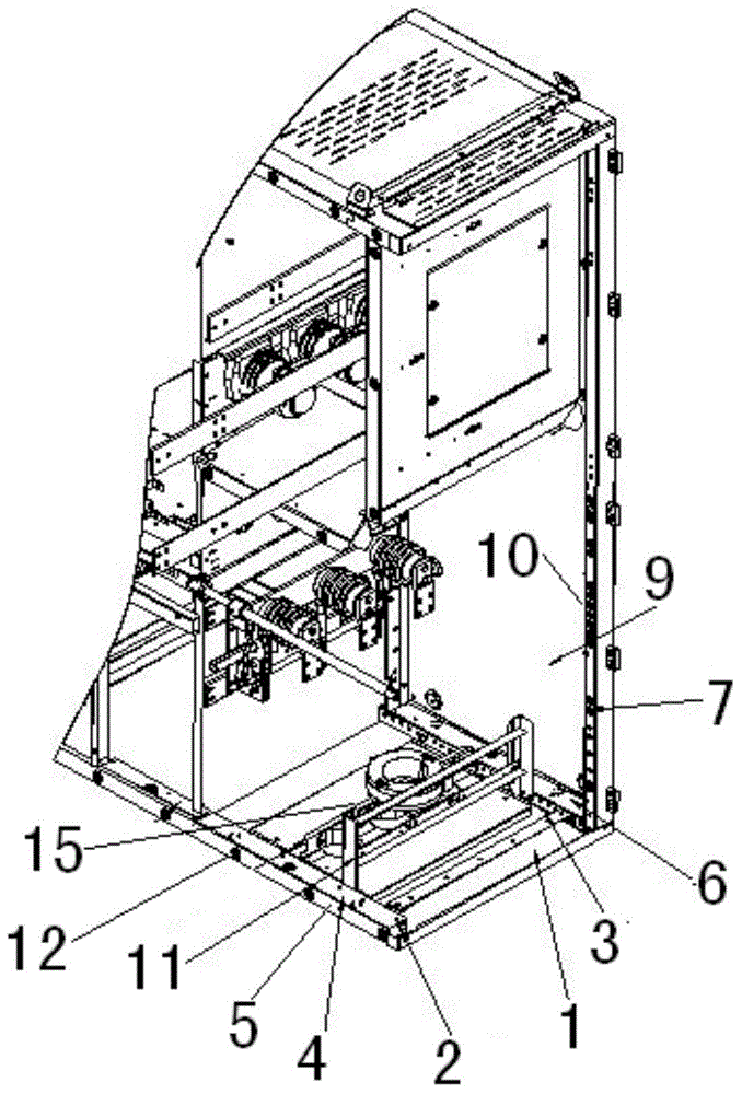
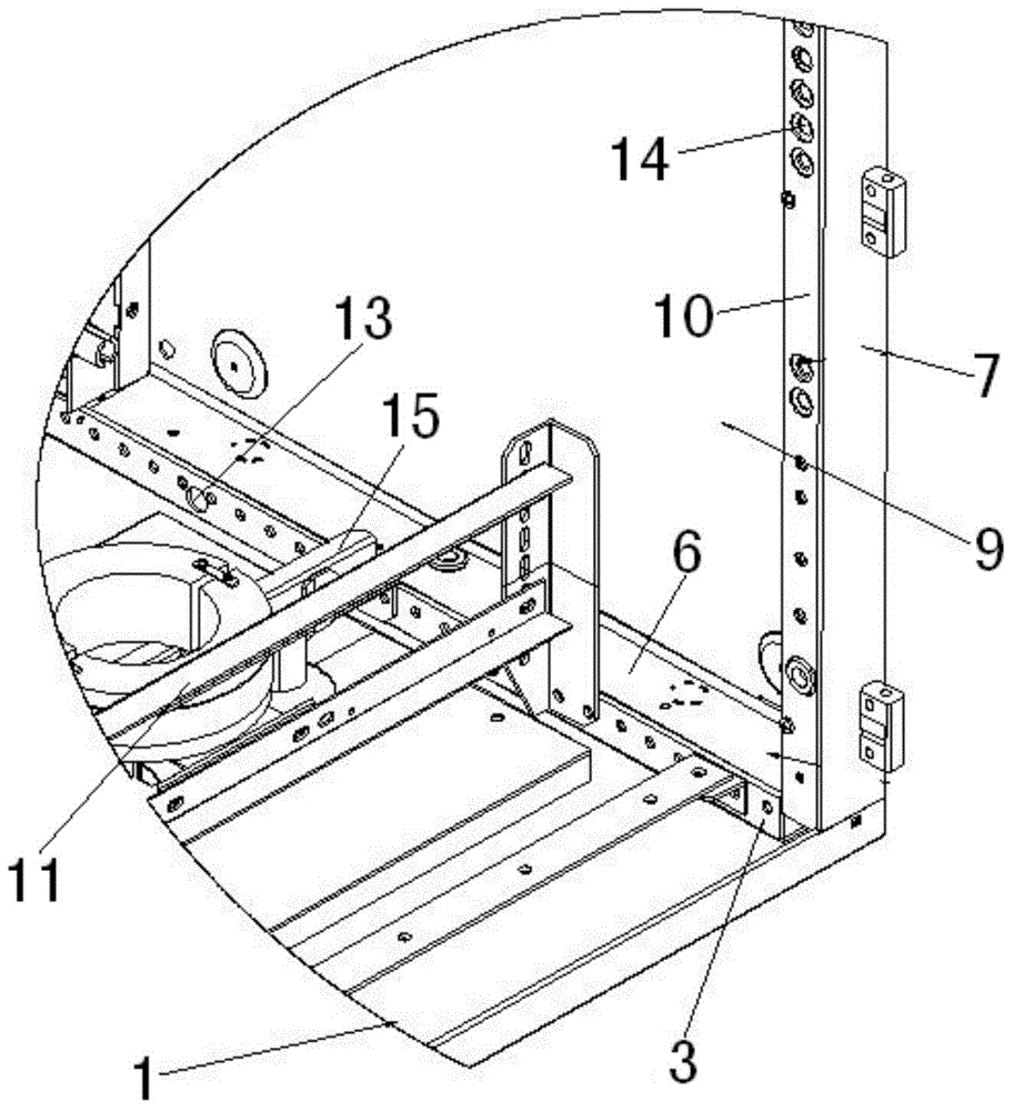
[0017] as attached figure 1 , attached figure 2 As shown, the present invention is an armored removable switchgear. The switchgear includes a base plate 1, a left base plate support 2 and a right base plate support 3 are respectively arranged on both sides of the base plate 1, and the left base plate support 2 and the right base plate support 3 are arranged respectively. The base plate supports 3 are all U-shaped structures in section, the bottom of the left base plate support 2 and the bottom of the right base plate support 3 are respectively connected with the base plate 1, and the left base plate support 2 and the...


PUM


Abstract

The invention provides a movable-type switch cabinet which is applied to a metal steel-clad movable-type high-voltage switch device. A left soleplate support (2) and a right soleplate support (3) of the switch cabinet are respectively of a structure with a U-shaped cross section, the bottom of the left soleplate support (2) and the bottom of the right soleplate support (3) are respectively connected with a soleplate (1), the left soleplate support (2) and the right soleplate support (3) are respectively provided with a soleplate secondary wiring cover plate (4) in a buckling manner, each soleplate secondary wiring cover plate (4) is of a structure with an L-shaped cross section, a bending part of one of the soleplate secondary wiring cover plate (4) is connected with the outer side surface of the left soleplate support (2), and the other soleplate secondary wiring cover plate (4) is connected to the outer side surface of the right soleplate support (3). The switch cabinet is simple in structure, the switch cabinet soleplate part and the secondary wiring device are optimized, the complexity in design, production, assembling and debugging can be alleviated, the assembling labor intensity can be alleviated, and the production cost also can be effectively reduced.

Description

technical field [0001] The invention belongs to the technical field of metal armored removable high-voltage switchgear, and more specifically relates to an armored removable switchgear. Background technique [0002] At present, in the power system, the bottom plate assembly of high-voltage switchgear is mainly composed of bottom plate brackets (left and right), bottom plate, zero sequence bracket, and cable clamp bracket. The secondary wiring device of the high-voltage switchgear is mainly composed of the left rear side plate, wiring groove, and wiring groove cover. The above two parts are usually distributed and assembled relatively independently, resulting in a large number of sheet metal parts constituting the device, and some sheet metal parts need to be bent many times, which not only brings a certain amount of tasks to the production assembly, but also improves the Cost of production. At the same time, since the secondary routing device is designed to be installed in...

Claims


Application Information

Patent Timeline
IPC IPC(8): H02B1/26H02B1/20
CPCH02B1/015H02B1/26
Inventor 束龙胜李开明余浩付强周波陆袁孟祥军王春玲王坤
Owner ANHUI ZHONGDIAN XINGFA & XINLONG TECH CO LTD
Why Eureka
Try Eureka