Supercharge Your Innovation With Domain-Expert AI Agents!

Plate tray stacking conveyor structure

A technology of accumulative conveying and pallets, which is applied in the structural field of plate-shaped pallet accumulative conveyors, can solve the problems of high cost of use, complex structure, occupation, etc., and achieve the effect of low cost of use and simple conveying structure

Inactive Publication Date: 2015-05-27
WUXI FORMEN TECHN
View PDF0 Cites 4 Cited by
  • Summary
  • Abstract
  • Description
  • Claims
  • Application Information

AI Technical Summary

Problems solved by technology

[0002] Plate-shaped pallets generally need to be piled up at the end of the conveyor after being conveyed, and they will be taken away together after reaching a certain amount. There is an existing chain traction accumulation conveyor, see image 3 As shown, it includes a roller bracket 1, a roller conveyor line 3 composed of a plurality of rollers 2 is respectively arranged on both sides of the roller bracket 1, a chain conveyor line 4 is arranged in the middle of the two roller conveyor lines 3, and a chain 5 of the chain conveyor line 4 Set a spring piece 6 at a certain distance, the height of the spring piece 6 is higher than the roller 2, the plate tray 7 is placed on the roller 2 and carried by the roller 2, it can slide freely, the chain 5 on the chain conveyor line 4 rotates, driving the spring The sheet 6 moves, and the spring sheet 6 pushes the plate-shaped tray 7 to move. When the plate-shaped tray 7 is transported to the end and is blocked, the resistance is greater than the thrust of the spring sheet 6. The spring sheet 6 is bent and slides from the bottom of the plate-shaped tray 7. The plate-shaped tray 7 realizes stacking, but its structure is complicated, and a chain conveyor line 4 needs to be installed in the middle of the roller conveyor line 3, and spring sheets 6 are arranged at intervals on the chain 5, the structure is complex, the use cost is high, and only plate trays can be realized. The stacking of trays 7 horizontally takes up too much conveying space

Method used


Image

  • Plate tray stacking conveyor structure
  • Plate tray stacking conveyor structure
  • Plate tray stacking conveyor structure

Examples


Embodiment Construction

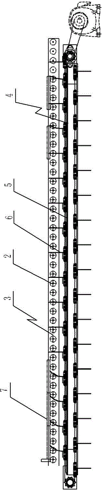
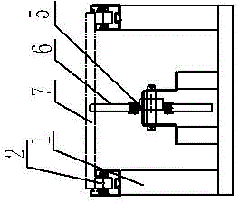
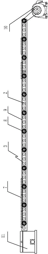
[0017] See image 3 , Figure 4 , Figure 5 As shown, a plate-shaped tray accumulation conveyor structure, which includes a roller bracket 1, the two sides of the roller bracket 1 are respectively provided with a roller conveyor line 3 composed of a plurality of rollers 2, and the roller conveyor line 3 on one side is separated by a certain number. The roller 2 is provided with a sprocket 8 coaxial with the roller 2, and the multiple sprockets 8 are connected by a conveyor belt 9, the sprocket 8 on one side of the roller conveyor line 3 is connected to the drive motor 10, and the end of the roller conveyor line 3 is connected to the tray receiving Device 11, the tray receiving device 11 includes a frame 12, a support wheel conveyor is arranged on the frame 12, the support wheel conveyor includes two support wheel conveying lines 13 arranged side by side, and two support wheel conveying lines 13 are arranged between The jacking cylinder 14, the racks 12 on both sides of the su...


PUM


Abstract

The invention relates to the technical field of conveying devices and particularly relates to a plate tray stacking conveyor structure. The structure is simple, low in utilization cost and capable of stacking plate trays vertically conveniently. The structure comprises a roller support, and a roller conveying line formed by a plurality of rollers is arranged on the two sides of the roller support respectively. The structure is characterized in that chain wheels coaxial with the rollers are arranged on the roller conveying line on one side at intervals of the certain number of rollers, a plurality of the chain wheels are connected through the conveying belt, and the chain wheels on one side of the roller conveying line are connected with a drive motor. Tray collection units are connected with the tail ends of the roller conveying lines and comprise racks. Support wheel conveyors are arranged on the racks and comprise two parallel support wheel conveying lines. At least two jacking cylinders are arranged between the two support wheel conveying lines, a translation carrier is arranged on the racks on the two sides of the support wheel conveyors respectively, and the translation carriers are connected with translation cylinders.

Description

technical field [0001] The invention relates to the technical field of conveying devices, in particular to a plate-shaped tray accumulating conveyor structure. Background technique [0002] Plate-shaped pallets generally need to be piled up at the end of the conveyor after being conveyed, and they will be taken away together after reaching a certain amount. There is an existing chain traction accumulation conveyor, see image 3 As shown, it includes a roller bracket 1, a roller conveyor line 3 composed of a plurality of rollers 2 is respectively arranged on both sides of the roller bracket 1, a chain conveyor line 4 is arranged in the middle of the two roller conveyor lines 3, and a chain 5 of the chain conveyor line 4 Set a spring piece 6 at a certain distance, the height of the spring piece 6 is higher than the roller 2, the plate tray 7 is placed on the roller 2 and carried by the roller 2, it can slide freely, the chain 5 on the chain conveyor line 4 rotates, driving the ...

Claims


Application Information

Patent Timeline
Patent Type & Authority Applications(China)
IPC IPC(8): B65G59/06
Inventor 田芸
Owner WUXI FORMEN TECHN
Features
  • R&D
  • Intellectual Property
  • Life Sciences
  • Materials
  • Tech Scout
  • Unparalleled Data Quality
  • Higher Quality Content
  • 60% Fewer Hallucinations
Learn More