Automatic collecting device of thin-wall U-shaped steel pipe and collecting method

An automatic collection, U-shaped technology, applied in the direction of object stacking, transportation and packaging, conveyor objects, etc., can solve the problems of deformation, no steel pipe collection and storage device, noisy steel pipes, etc.

Active Publication Date: 2010-05-12
北京中冶设备研究设计总院有限公司
View PDF1 Cites 7 Cited by
  • Summary
  • Abstract
  • Description
  • Claims
  • Application Information

AI Technical Summary

Problems solved by technology

[0002] Most of the existing steel pipe collection is realized by the collection frame method. During the steel pipe collection process, steel pipes often collide with each other to generate noise and deformation of the steel pipe, which seriously affects the health of the operator and the quality of the steel pipe.
The 200820027753.1 patent improves the collection device used in the above-mentioned steel pipe collection method, and provides a steel pipe collection device (such as Figure 8 shown) includes rocker arm, pull rope, trolley, guide rail, steel wire rope, support frame, base, cylinder and other components. Under the action of cylinder, steel wire rope and trolley, the device produces buffer and reduces the noise generated duri

Method used


Image

  • Automatic collecting device of thin-wall U-shaped steel pipe and collecting method
  • Automatic collecting device of thin-wall U-shaped steel pipe and collecting method
  • Automatic collecting device of thin-wall U-shaped steel pipe and collecting method

Examples


Embodiment Construction

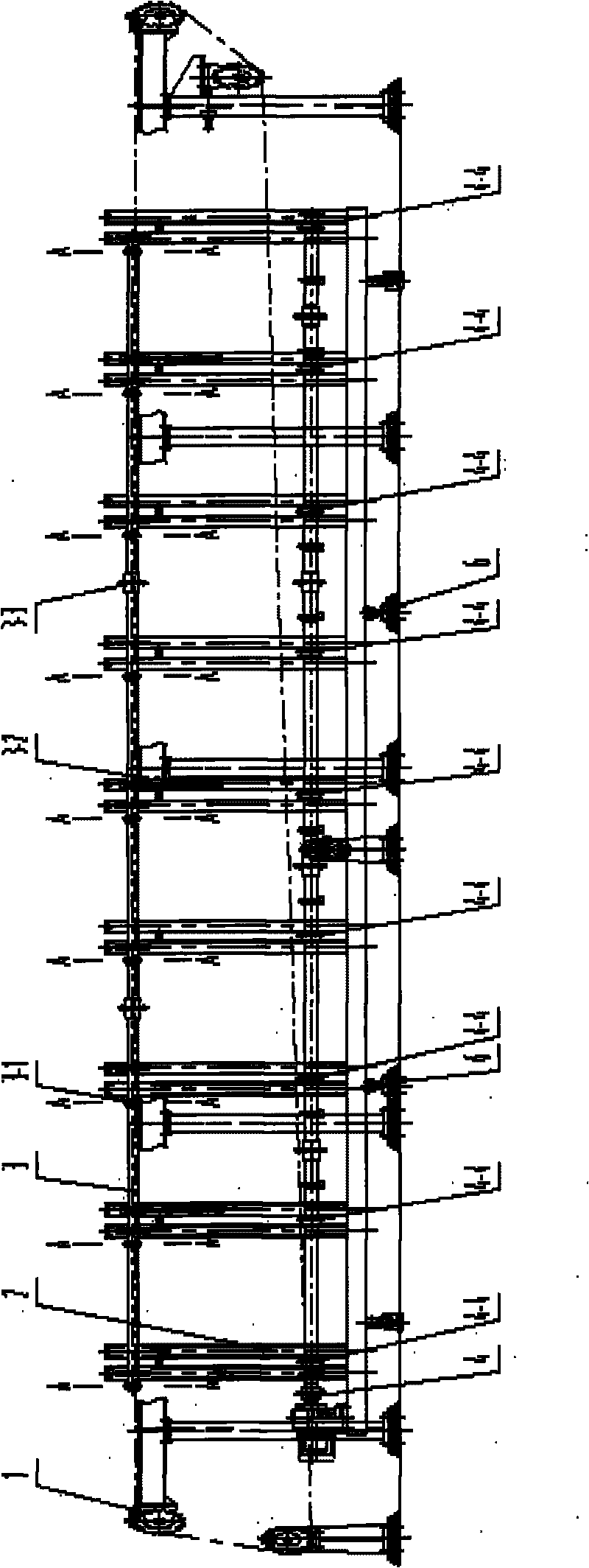
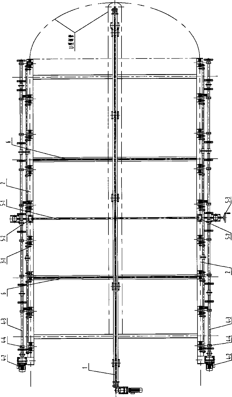
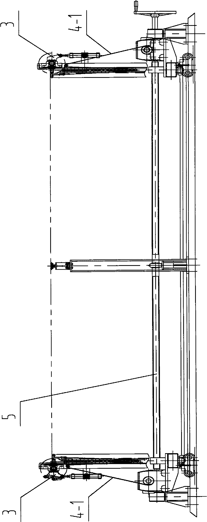
[0015] Embodiment of the present invention will be described in further detail below in conjunction with accompanying drawing: Figure 1 to Figure 8 A thin-walled U-shaped steel pipe automatic collection device shown includes a chain unloading device 1, a steel pipe support 2 and a rolling support 3-1, a cylinder 3-2, and a synchronous shaft 3-3 installed on the steel pipe support 2 Cylinder swinging device 3, flat sling 4-1 is installed, drive motor 4-2, drive shaft 4-3, flat sling collecting device 4 of reel 4-4 and screw mandrel 5- with left and right rotation 1. Screw nut 5-2, handwheel 5-3 manual adjustment device 5, linear guide rail 6 fixedly installed on the foundation; the positions corresponding to the linear guide rail 6 on both sides of the bottom of the steel pipe bracket are installed with rollers that can slide along the linear guide rail A method for automatic collection of thin-walled U-shaped steel pipes, characterized in that: after the chain unloading devic...


PUM


Abstract

An automatic collecting device of a thin-wall U-shaped steel pipe is characterized by comprising a chain feed device, a steel pipe bracket, an air cylinder oscillating device with a rolling support, an air cylinder and a synchronous shaft, a webbing sling collecting device with a webbing sling, a driving motor, a driving shaft and a winding drum and an adjusting device consisting of a manual screw rod, a screw with thread and a hand wheel. The automatic thin-wall U-shaped steel pipe collecting method is characterized by: after taking materials through the chain, using the rolling support for delivering the U-shaped steel pipe to an L-shaped hook of the chain so that the chain completely detaches from the steel pipe; then supporting the U-shaped steel pipe by the rolling support to realize the feed of the steel pipe; subsequently causing the air cylinder to act so that the synchronous shaft drives the rolling support to swing; and putting the U-shaped steel pipe on the webbing sling and then starting the motor and using the driving shaft and the winding drum to descend the U-shaped steel pipe on the webbing sling to a certain height, thus realizing the stacked collection of U-shaped steel pipes. The method and the device achieve the effect of meeting the requirement for collecting large-size U-shaped thin-wall steel pipe during the processes of hoisting, storing, packaging and transporting.

Description

Technical field: [0001] The invention relates to a steel pipe production auxiliary equipment, in particular to an automatic collection device and a collection method for thin-walled U-shaped steel pipes in nuclear power equipment, boilers and pressure vessels. Background technique: [0002] Most of the existing steel pipes are collected by means of collection frames. During the collection of steel pipes, steel pipes often collide with each other to generate noise and deformation of the steel pipes, seriously affecting the health of the operator and the quality of the steel pipes. The 200820027753.1 patent improves the collection device used in the above-mentioned steel pipe collection method, and provides a steel pipe collection device (such as Figure 8 shown) includes rocker arm, pull rope, trolley, guide rail, steel wire rope, support frame, base, cylinder and other components. Under the action of cylinder, steel wire rope and trolley, the device produces buffer and reduce...

Claims


Application Information

Patent Timeline
IPC IPC(8): B65G47/34B65G57/02B65G57/20
Inventor 徐勇王军杨良文王国平
Owner 北京中冶设备研究设计总院有限公司
Why Eureka
Try Eureka