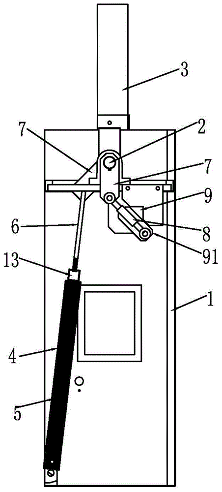
A road gate machine with the buffer function of the brake rod lower rod
A technology of barrier gates and buffer mechanisms, applied in the field of barrier gates, can solve problems such as ineffective buffer control, damage to barrier gates, and easy accidental injury to others, and achieve good buffer control effects, low production costs, and easy adjustments
- Summary
- Abstract
- Description
- Claims
- Application Information
AI Technical Summary
Problems solved by technology
Method used
Image
Examples
Embodiment 1
[0034] refer to Figure 1 to Figure 5 Shown is a barrier gate machine with the buffering function of the lower bar of the brake lever, including a cabinet 1, a rotating shaft 2 and a brake lever 3. The brake lever 3 is provided with a main spring 4 and a secondary spring 5. The main spring 4 and the The auxiliary spring 5 is connected to the brake lever 3 through a pull rod 6, the active force of the main spring 4 and the brake lever 3 maintain a pulling state, and the active force of the auxiliary spring 5 only pulls the brake when the brake lever 3 is lowered to a certain angle. lever to increase the pulling force of the brake lever 3, such as the secondary spring 5 when the main spring 4 pulls the brake lever 3 down to about half of the position (that is, the brake lever 3 is lowered by 30°, 35°, 40°, 45°, 50° or 55° position), the auxiliary spring 5 starts to pull the brake lever, which serves as a supplement for the tension of the main spring 4, and the force of the auxil...
Embodiment 2
[0039] refer to Figure 6 to Figure 9As shown, a barrier gate with the buffer function of the brake rod and the lower rod has the technical characteristics that: a connecting block 10 is arranged between the main spring 4 and the auxiliary spring 5, and the main spring 4 and the auxiliary spring 5 The upper and lower sides of the connecting block 10 are respectively arranged to form a brake rod descending deceleration buffer mechanism with an up-and-down structure; a baffle plate 11 is provided on the chassis 1 corresponding to the buffer mechanism, and one end of the buffer mechanism is installed on a fixed position of the chassis 1 , the other end of which is connected to the tie rod 6 of the connecting block 10 and passes through the baffle plate 11 to connect with the brake lever 3, so that the active force of the main spring 4 distributed on the upper and lower positions of the connecting block 10 and the active force of the secondary spring 5 are opposite. There is a dis...
Embodiment 3
[0042] refer to Figure 10 to Figure 13 The barrier gate with the buffer function of the lower rod of the brake rod shown in the figure is characterized in that: the main spring 4 and the auxiliary spring 5 are provided with a fixed block 12, and one end of the main spring 4 is fixed on the chassis 1 On the fixed position, the other end is installed on the fixed block 12; one end of the auxiliary spring 5 is fixed on the fixed position of the chassis 1, and one end of the pull rod 6 is provided with a bulging protruding head 2 61, and the bulging protruding head 2 61 Suspended in the middle of the auxiliary spring 5, the pull rod 6 forms a section of empty travel distance in the auxiliary spring 5, and the other end of the pull rod 6 passes through the fixed block 12 where the main spring 4 is installed to connect with the brake lever 3. There is a nut at the tail end of the pull rod 6, which is suspended in the middle of the secondary spring 5, so that the pull rod has a idli...
PUM
 Abstract
Description
Claims
Application Information
 - R&D Engineer
- R&D Manager
- IP Professional
- Industry Leading Data Capabilities
- Powerful AI technology
- Patent DNA Extraction
Browse by: Latest US Patents, China's latest patents, Technical Efficacy Thesaurus, Application Domain, Technology Topic, Popular Technical Reports.
© 2024 PatSnap. All rights reserved.Legal|Privacy policy|Modern Slavery Act Transparency Statement|Sitemap|About US| Contact US: help@patsnap.com


