
Barrie gate machine with gate rod lower rod buffering function

A technology of barrier gates and buffer mechanisms, applied in the field of barrier gates, can solve problems such as ineffective buffer control, damage to barrier gates, and easy accidental injury to others, and achieve good buffer control effects, low production costs, and easy adjustments

Inactive Publication Date: 2015-05-27
张振滔 +1
View PDF8 Cites 0 Cited by
  • Summary
  • Abstract
  • Description
  • Claims
  • Application Information

AI Technical Summary

Problems solved by technology

[0002] The gate machine is mainly composed of a chassis, a rotating shaft and a gate lever. Due to the weight of the gate lever and the inertia of the lower lever, when the gate lever is lowered, the lever is often quickly lowered to produce an impact, which may easily cause damage to the gate machine or even accidentally injure others. , therefore, in order to avoid this technical problem of the barrier gate, it is of great significance to set up a buffer device for the barrier gate
However, the existing buffer control technology of barrier gates adopts hydraulic transmission control, servo, frequency conversion motor or gear reduction box control, but whether it is hydraulic transmission control or servo, frequency conversion motor or gear reduction box control, its structure is relatively complicated, and the cost is relatively high. High, many faults, and buffer control effect is not obvious

Method used


Image

  • Barrie gate machine with gate rod lower rod buffering function
  • Barrie gate machine with gate rod lower rod buffering function
  • Barrie gate machine with gate rod lower rod buffering function

Examples


Embodiment 1

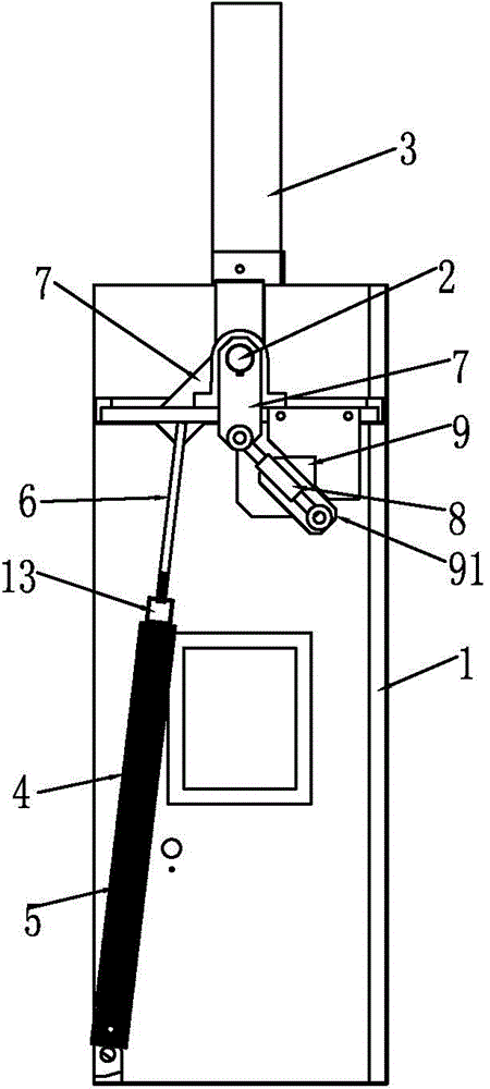
[0033] refer to Figure 1 to Figure 5 Shown is a barrier gate machine with the buffering function of the lower bar of the brake lever, including a cabinet 1, a rotating shaft 2 and a brake lever 3. The brake lever 3 is provided with a main spring 4 and a secondary spring 5. The main spring 4 and the The auxiliary spring 5 is connected to the brake lever 3 through a pull rod 6, the active force of the main spring 4 and the brake lever 3 maintain a pulling state, and the active force of the auxiliary spring 5 only pulls the brake when the brake lever 3 is lowered to a certain angle. lever to increase the pulling force of the brake lever 3, such as the secondary spring 5 when the main spring 4 pulls the brake lever 3 down to about half of the position (that is, the brake lever 3 is lowered by 30°, 35°, 40°, 45°, 50° or 55° position), the auxiliary spring 5 starts to pull the brake lever, which serves as a supplement for the tension of the main spring 4, and the force of the auxil...

Embodiment 2

[0038] refer to Figure 6 to Figure 9As shown, a barrier gate with the buffer function of the brake rod and the lower rod has the technical characteristics that: a connecting block 10 is arranged between the main spring 4 and the auxiliary spring 5, and the main spring 4 and the auxiliary spring 5 The upper and lower sides of the connecting block 10 are respectively arranged to form a brake rod descending deceleration buffer mechanism with an up-and-down structure; a baffle plate 11 is provided on the chassis 1 corresponding to the buffer mechanism, and one end of the buffer mechanism is installed on a fixed position of the chassis 1 , the other end of which is connected to the tie rod 6 of the connecting block 10 and passes through the baffle plate 11 to connect with the brake lever 3, so that the active force of the main spring 4 distributed on the upper and lower positions of the connecting block 10 and the active force of the secondary spring 5 are opposite. There is a dis...

Embodiment 3

[0041] refer to Figure 10 to Figure 13 The barrier gate with the buffer function of the lower rod of the brake rod shown in the figure is characterized in that: the main spring 4 and the auxiliary spring 5 are provided with a fixed block 12, and one end of the main spring 4 is fixed on the chassis 1 On the fixed position, the other end is installed on the fixed block 12; one end of the secondary spring 5 is fixed on the fixed position of the chassis 1, and the tail end of the pull rod 6 has a nut, which is suspended in the middle of the secondary spring 5, so that the pull rod is in the secondary spring There is a section of idling stroke, the middle part of the pull rod 6 is fixed with the fixed block 12 where the main spring 4 is installed, and is connected with the rotating piece 7 of the brake rod 3 by the pull rod 6 to drive the brake rod 3 to lift. Its working principle is the same as that of Embodiment 1, and the rest are the same as those of Embodiment 1.


PUM


Abstract

The invention provides a barrier gate machine with a gate rod lower rod buffering function, belongs to the field of barrier gates (advertisement barrier gates), and particularly relates to the barrier gate machine with the gate rod lower rod buffering function. The barrier gate machine comprises a machine box, a rotary shaft and a gate rod, wherein the gate rod is provided with a main spring and a secondary spring; the main spring and the secondary spring are connected with the gate rod by a pull rod; the acting force of the main spring keeps a pulling state with the gate rod; the acting force of the secondary spring enters a pulling state when a gate rod lower rod moves to a certain angle; the acting force of the secondary spring is used for supplementing the tension of the main spring so that a buffering mechanism for decelerating the gate rod lower rod is formed by the main spring and the secondary spring. When the barrier gate machine is used, the barrier gate machine can be descended stably and has a good buffering control effect; the structure is simple and the production cost is low.

Description

technical field [0001] The invention belongs to the field of barrier gates (advertising barrier gates), and in particular relates to a barrier gate machine with the function of buffering the lower rod of the brake rod. Background technique [0002] The gate machine is mainly composed of a chassis, a rotating shaft and a gate lever. Due to the weight of the gate lever and the inertia of the lower lever, when the gate lever is lowered, the lever is often quickly lowered to produce an impact, which may easily cause damage to the gate machine or even accidentally injure others. , Therefore, in order to avoid this technical problem of the barrier gate, it is of great significance to set up a buffer device for the barrier gate. However, the existing buffer control technology of barrier gates adopts hydraulic transmission control, servo, frequency conversion motor or gear reduction box control, but whether it is hydraulic transmission control or servo, frequency conversion motor or...

Claims


Application Information

Patent Timeline
Patent Type & Authority Applications(China)
IPC IPC(8): E01F13/06
CPCE01F13/06
Inventor 张振滔曾泽林
Owner 张振滔
Learn More