
Novel assembled shear wall structure

A shear wall, prefabricated technology, applied in the direction of walls, building components, building structures, etc., can solve the problems of unclear and reduced vertical continuous force transmission, achieve clear force transmission paths, simple construction operations, and solve the problem of vertical continuous force transmission. Unclear effect to continuous force transmission

Active Publication Date: 2015-05-27
SHENYANG JIANZHU UNIVERSITY
View PDF6 Cites 21 Cited by
  • Summary
  • Abstract
  • Description
  • Claims
  • Application Information

AI Technical Summary

Problems solved by technology

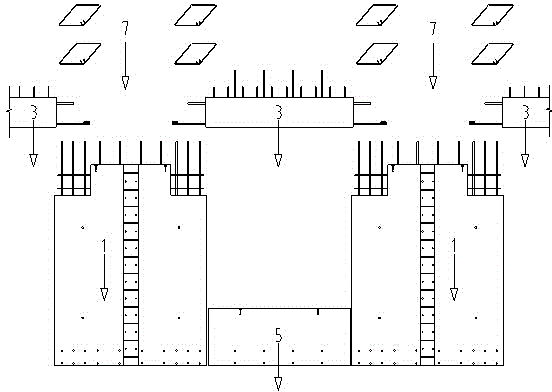
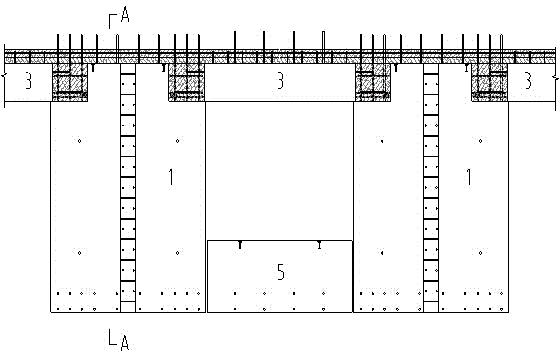
[0004] The purpose of this invention is to provide a prefabricated concrete shear wall structure. The core content is that the outer wall is almost completely prefabricated (except for some vertical cast-in-place sections of the corner wall), and the cast-in-place part is set on the inner wall. The prefabricated beam and the prefabricated external wall cast-in-place connection are set within the range of the reserved beam socket of the shear wall, and the wall panel under the prefabricated window is connected to the lower connecting beam through the grouting sleeve, so that the on-site operation is simple and the external The wall formwork project and cast-in-place operations are significantly reduced, and all prefabricated components are in-line shape. The production and installation of components are simple, and the force transmission path is clear. The key problem of unclear force transmission to the continuum

Method used


Image

  • Novel assembled shear wall structure
  • Novel assembled shear wall structure
  • Novel assembled shear wall structure

Examples


Embodiment Construction

[0023] The split system of the assembled shear wall structure proposed by the present invention is as follows:

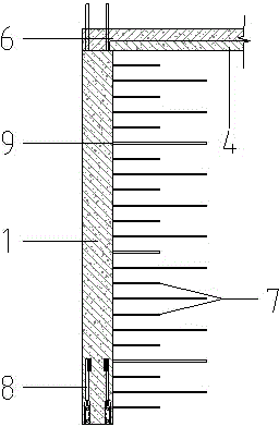
[0024] 1. Prefabricated exterior wall panels 1 are prefabricated with flanges at the joints of corner walls, as shown in the attached Figure 5 shown. The edge component stirrups 7 and horizontally distributed steel bars 9 are reserved through the prefabricated exterior wall panel 1, and are connected with the horizontally distributed steel bars 9 left by the prefabricated external wall panel in the other direction in the cast-in-place area. The length of the cast-in-place part 6 is distributed horizontally. The minimum lap length of the reinforcement is determined. The on-site installation sequence is as follows: after the prefabricated exterior wall panel 1 is installed and positioned, the horizontally distributed steel bars 9 of the prefabricated external wall panel 1 in the other direction should be split outward in advance, and the horizontally distribute...


PUM


Abstract

The invention discloses a novel assembled shear wall structure. The novel assembled shear wall structure comprises prefabricated shear walls, prefabricated beams, prefabricated slabs, prefabricated wallboards under windows and cast-in-situ nodes. External walls are fully prefabricated, and internal walls are prefabricated or cast in situ. Flanges of the T-shaped nodes are prefabricated, a cast-in-situ section area is arranged for webs, or all the webs are cast in situ; the flanges of the L-shaped nodes are prefabricated, a cast-in-situ section area is arranged for the non-prefabricated parts, and the length of the cast-in-situ section is determined according to the minimum splicing length of horizontally distributed reinforcing steel bars. When the shear walls are connected with connection beams, beam sumps are reserved on the wallboards of the shear walls in advance, the lengths of the beam sumps are determined according to the linear anchoring lengths of the bottom ribs of the connection beams, and connection nodes are cast in situ. The length of the cast-in-situ part at the seam of the shear walls is determined according to the minimum operating space for binding the reinforcing steel bars on construction site. The wallboards under windows are prefabricated wallboards under windows; reinforcing steel bar connection sleeves are pre-embedded in the bottom parts of the wallboards, and connected with the pre-reserved reinforcing steel bars on the prefabricated connection beams through grouting sleeves. All prefabricated members are I-shaped, and the members are convenient to produce and transport, and simple to install on site.

Description

technical field [0001] The present invention relates to the field of prefabricated concrete structures, specifically a new type of prefabricated shear wall structure, which is a prefabricated assembly integral type (hereinafter Assembly type for short) mixed [0002] Concrete shear wall structures, member connection structures, structures built by such split systems and connection structures. Background technique [0003] The existing splits of prefabricated shear wall structures are mainly "cast-in-site edge components, prefabricated non-edge components" and "partial cast-in-place edge components, horizontal steel bar connecting ring rings", "cast-in-site edge components, non-edge components The horizontally distributed reinforcement of the wall in the split method of prefabrication cannot be anchored like cast-in-place, and the stirrups of the edge members will bear the horizontal shear force, which is different from the design idea of ​​cast-in-place structures. ...

Claims


Application Information

Patent Timeline
IPC IPC(8): E04B2/00E04B2/72E04B2/84
Inventor 刘海成李红旺杜明辉韩冬阳任旭秦庚
Owner SHENYANG JIANZHU UNIVERSITY
Learn More