
Cooling device of slag cooler

A technology of cooling device and slag cooler, applied in the field of cooling device, can solve the problems of difficult to ensure sealing at the joint, axial movement of the central shaft, affecting the sealing performance, etc., to prevent axial movement, reliable rotation, smooth flow effect

Inactive Publication Date: 2015-05-27
张家港市金昌龙机械设备有限公司
View PDF4 Cites 0 Cited by
  • Summary
  • Abstract
  • Description
  • Claims
  • Application Information

AI Technical Summary

Problems solved by technology

One end of the central shaft is connected to the liquid inlet pipe, and the other end is connected to the liquid outlet pipe. The cooling path is short and the cooling effect is poor. At the same time, the central shaft rotates with the drum, and it is difficult to ensure the sealing at the connection. At the same time, the high-speed rotating bearing of the central shaft is easy to wear, and the central shaft Axial movement is prone to occur, affecting sealing performance

Method used


Image

  • Cooling device of slag cooler

Examples


Embodiment Construction

[0017] The present invention will be described in further detail below through specific examples.

[0018] The upstream and downstream mentioned in the present invention are determined by the flow direction of the cooling liquid in the central liquid inlet pipe 5 .

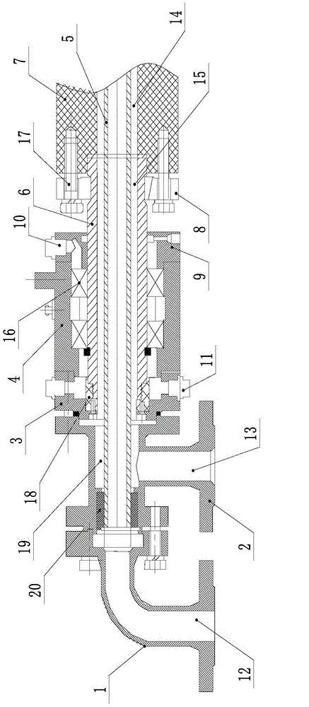
[0019] Such as figure 1 As shown, a cooling device for a slag cooler includes a liquid inlet pipe seat 1, a liquid return pipe seat 2, a bearing seat, a central liquid inlet pipe 5, and a rotating liquid return pipe 6. The liquid inlet pipe seat 1 and the liquid return pipe The pipe base 2 is fixedly connected, and the fixed connection adopts bolt connection, which is convenient for disassembly. The liquid inlet pipe seat 1 is provided with a liquid inlet port 12, and the liquid return pipe seat 2 is provided with a liquid return port 13 and a liquid return through hole. 19. Generally speaking, the cooling slag machine is cooled by cooling water. Therefore, what flows in the liquid inlet pipe seat 1, the central ...


PUM


Abstract

The invention discloses a cooling device of a slag cooler. The cooling device comprises a liquid-inlet pipe base, a liquid-return pipe base, a bearing block, a central liquid-inlet pipe and a rotary liquid-return pipe, wherein a liquid inlet is formed in the liquid-inlet pipe base; a liquid-return opening and a liquid-return through hole are formed in the liquid-return pipe base; an inner hole is formed in the bearing block; the rotary liquid-return pipe is rotationally arranged in the inner hole of the beating block through a bearing; the central liquid-inlet pipe is arranged in the rotary liquid-return pipe; the upstream end of the central liquid-inlet pipe is communicated with the liquid inlet; the inner hole of the rotary liquid-return pipe and the outer wall of the central liquid-inlet pipe form a liquid-return passage; the liquid-return passage is communicated with the liquid-return through hole and the liquid-return opening; the downstream end of the central liquid-inlet pipe penetrates through a central shaft of the slag cooler; the rotary liquid-return pipe is fixedly connected with the central shaft; a liquid-return shaft hole of the central shaft is communicated with the liquid-return passage. According to the cooling device, cooling liquid can be effectively guaranteed to circularly flow in the slag cooler, the sealing property is guaranteed, maintenance is convenient to perform, and the cooling effect is improved.

Description

technical field [0001] The invention relates to a cooling device, in particular to a cooling device of a slag cooler. Background technique [0002] The current slag cooling machine generally includes a bracket and a drum. The drum is provided with a driving roller and at least two driven rollers. The bracket is provided with a supporting wheel, and the roller is rotatably connected to the supporting wheel. The bracket is provided with a base. The base is provided with a motor connected to the drive roller ring, the upstream end of the drum is provided with a feed pipe, the downstream end of the drum is provided with a discharge pipe, the drum is provided with a spiral piece along the axial direction, and the downstream end of the drum is provided with a feed pipe along the center line of the drum. The central shaft extending to the upstream end of the drum to the left, the part of the central shaft in the drum is fixedly connected with the spiral piece, the central shaft is ...

Claims


Application Information

Patent Timeline
Patent Type & Authority Applications(China)
IPC IPC(8): F23J1/06F23C10/24
Inventor 陆明秋
Owner 张家港市金昌龙机械设备有限公司
Learn More