Outdoor unit

A technology of outdoor unit and power distribution unit, which is applied in household heating, lighting and heating equipment, space heating and ventilation, etc. It can solve the problems of cooling air flow deterioration and difficult cooling air discharge.

Inactive Publication Date: 2010-07-21
SANYO ELECTRIC CO LTD
View PDF1 Cites 0 Cited by
  • Summary
  • Abstract
  • Description
  • Claims
  • Application Information

AI Technical Summary

Problems solved by technology

[0007] Conventionally, the outside air is vented into the machine room to cool the power distribution products in the power distribution box. However, if the power distribution box is arranged on the front side of the machine room as mentioned above, it is sometimes difficult to smoothly exchange the cooling air in the machine room with the heat. Indoor exhaust, the flow of cooling air may deteriorate

Method used


Image

  • Outdoor unit
  • Outdoor unit
  • Outdoor unit

Examples


Embodiment Construction

[0036] Embodiments of the present invention will be described in detail below with reference to the accompanying drawings.

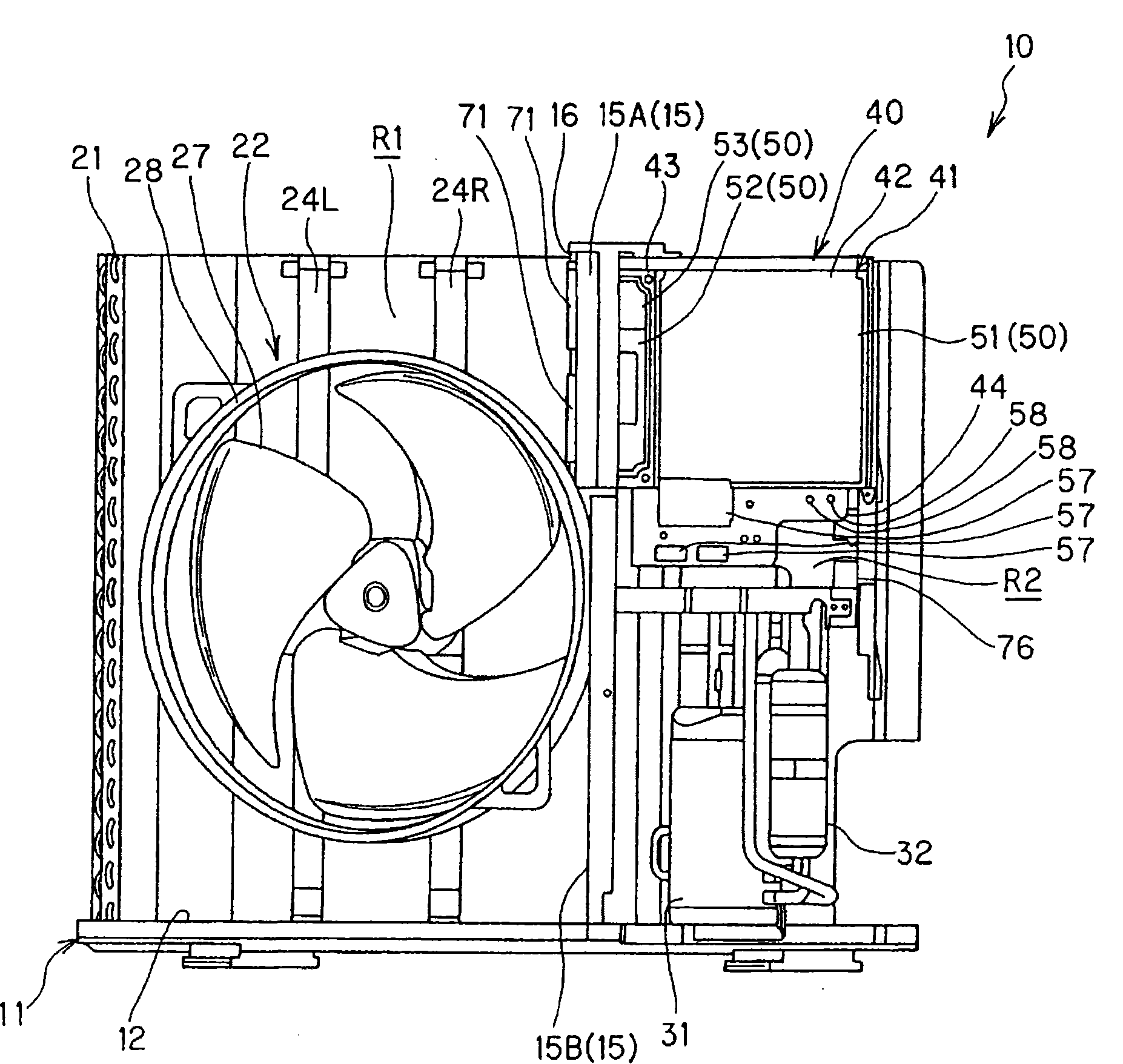
[0037] The air conditioner of this embodiment is composed of an outdoor unit 10 and an indoor unit (not shown), and refrigerant flows in a refrigerant circuit connected by refrigerant piping to perform cooling operation and heating operation. The outdoor unit 10 is installed outdoors, and condenses the refrigerant to release heat to the outside air during cooling operation by exchanging heat with outdoor air, and absorbs heat from the outside air by evaporating the refrigerant during heating operation. The directions of up and down and left and right described below represent directions when the outdoor unit 10 is installed and viewed from the front side thereof.

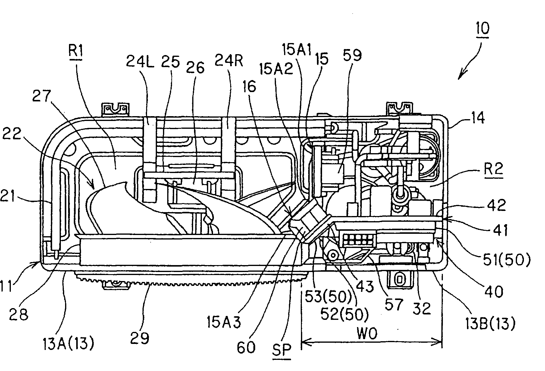
[0038] figure 1 It is a diagram of the outdoor unit 10 viewed from the front, figure 2 It is a figure which looked at the outdoor unit 10 from above. The outdoor unit 10 is provided with a...


PUM


Abstract

The invention provides an outdoor unit which can seek for reducing the projection area in front of distribution box and for smoothening the flowing of a cooling air that cools a mechanical chamber. The outdoor unit of the invention convexly bends part of the front edge of a spacing board (15) to the side of a heat exchanging chamber (R1) to form an inclined L shape, approximately and it has a distribution unit bearing plate (41). The distribution unit bearing plate extends from the outer side of the mechanical chamber (R2) to the side of the heat exchanging chamber and is formed by bending tothe front side of the heat exchanging chamber along the shape of the inclined L-shaped part (16). The end portion thereof is connected with the spacing plate. A blind-hole space SP surrounding by thebending part (15A2) of the bearing plate and the inclined L-shaped part of the spacing plate is equipped with a radiator (60) that outputs the heat of the distribution unit (52) that is supported by the distribution unit bearing plate. The inclined L-shaped part of the spacing plate is provided with ventilation holes (70), (71) in order to conduct the cooling air flowing in the back of the distribution unit bearing plate to cool the radiator to the negative side of the ventilator (22) of the heat exchanging chamber.

Description

technical field [0001] The present invention relates to an outdoor unit in which the inside of the unit housing is divided longitudinally by partition plates into a heat exchange chamber and a machine room, the heat exchange room houses a heat exchanger and a blower, and the machine room houses a compressor and a power distribution box. Background technique [0002] Some of the outdoor units of the air conditioner divide the inside of the unit casing into a heat exchange chamber and a machine room by partitioning vertically. The heat exchange room houses a heat exchanger and a blower, and the machine room houses a compressor and a power distribution box. [0003] Generally, this kind of power distribution box removes the front panel of the outdoor unit for maintenance work. Therefore, for example, when the power distribution box is set as a plate member extending substantially straight in the width direction of the machine room, as long as the power distribution product is a...

Claims


Application Information

Patent Timeline
Patent Type & Authority Patents(China)
IPC IPC(8): F24F1/00F24F1/24F24F5/00
Inventor 田村隆明
Owner SANYO ELECTRIC CO LTD
Why Eureka
Try Eureka