
Lubricating oil channel structure of internal combustion engine

A lubricating oil channel and internal combustion engine technology, which is applied in the direction of engine cooling, mechanical equipment, engine components, etc., can solve the problems of reducing the output power of the internal combustion engine, reducing the charging efficiency, etc., and achieve the effect of reliable flow

Active Publication Date: 2019-05-31
SUZUKI MOTOR CORP
View PDF9 Cites 0 Cited by
  • Summary
  • Abstract
  • Description
  • Claims
  • Application Information

AI Technical Summary

Problems solved by technology

[0006] Further, in the conventional lubricating oil passage structure, the part of the lubricating oil passage for cooling the cylinder head, which reaches the periphery of the spark plug, passes near the intake port, so the part of the lubricating oil passage for cooling the cylinder head passes through the discharge The heat of the gases reduces the charging efficiency by warming the intake air, which can reduce the output power of the internal combustion engine

Method used


Image

  • Lubricating oil channel structure of internal combustion engine
  • Lubricating oil channel structure of internal combustion engine
  • Lubricating oil channel structure of internal combustion engine

Examples


Embodiment Construction

[0027] refer to Figures 1 to 9 An embodiment of the lubricating oil passage structure of an internal combustion engine according to the present invention will be described.

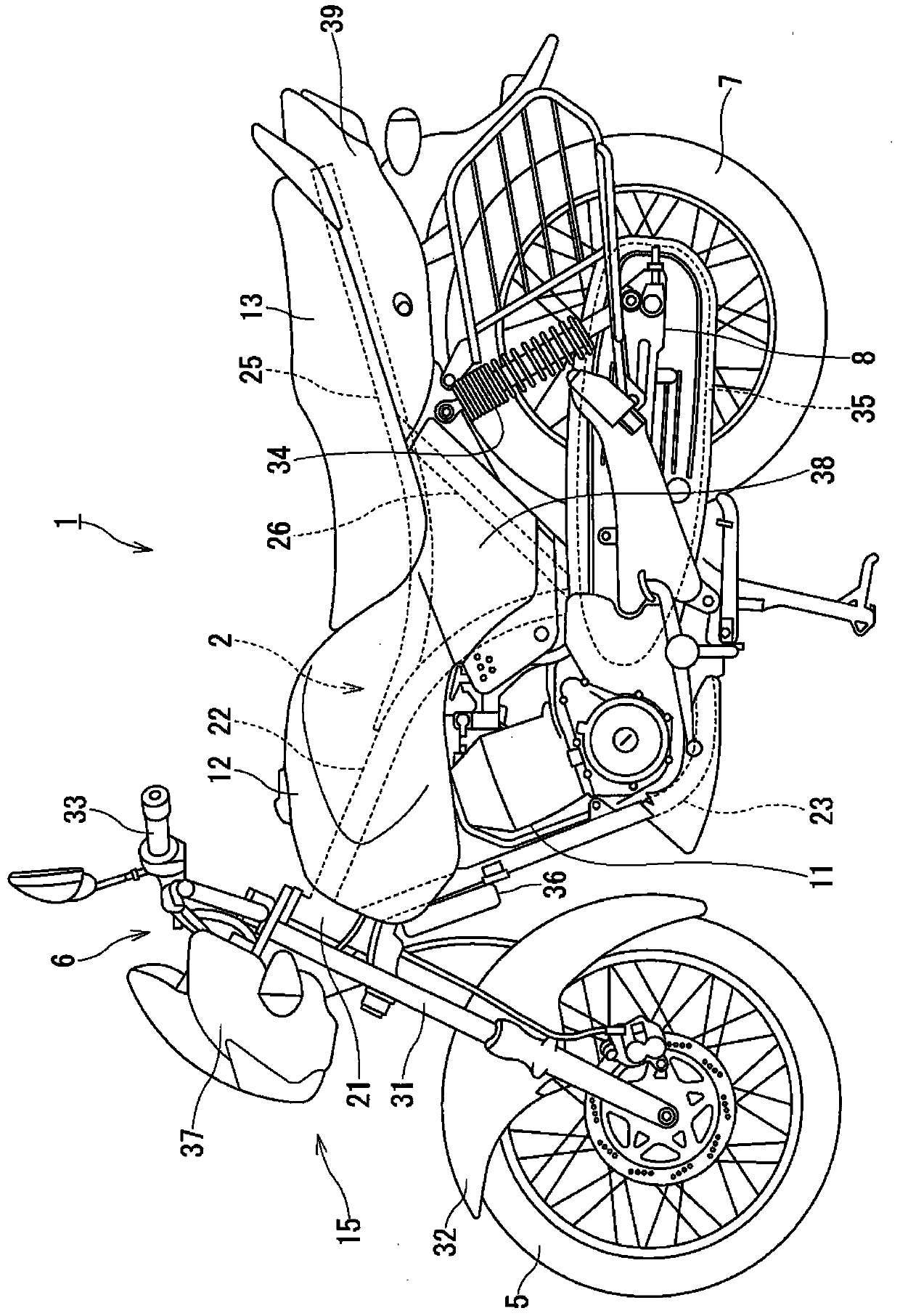
[0028] figure 1 is a left side view showing an example of a motorcycle to which a lubricating oil passage structure for an internal combustion engine according to an embodiment of the present invention is applied.

[0029] Note that in this embodiment, the representations of front and rear, up and down, left and right refer to the perspective of the driver on the motorcycle 1 .

[0030] Such as figure 1 As shown, the motorcycle 1 according to this embodiment includes: a body frame 2, which extends from front to rear; a front wheel 5, which is arranged in front of the body frame 2; a steering mechanism 6, which is arranged on the body The front end portion of the frame 2 and rotatably supports the front wheel 5; the rear wheel 7 is arranged behind the vehicle body frame 2; the swing arm 8 is arranged a...


PUM


Abstract

Provided is a lubricating oil passageway structure of an internal combustion engine. The lubricating oil passageway structure of the internal combustion engine generates reliable flow of oil around a cooling exhausting port. The lubricating oil passageway structure of an engine (11) comprises a lubricating oil passageway (56) disposed in a crankcase (41), a cylinder (42), and a cylinder cover (43) receiving a valve mechanism (61); and an oil cooler (36) cooling oil flowing in the lubricating oil passageway (56). A lubricating oil passageway (56c) in the cylinder cover (43) has a fourth lubricating oil passageway (76) used as an exhausting port cooling part. The fourth lubricating oil passageway enables oil exiting the lubricating oil passageway (56b) in the cylinder (42) to circulate around an exhausting port (65) and deliver the oil to the lubricating oil passageway (56b) in the cylinder (42). The exhausting port is disposed in the cylinder cover (43).

Description

[0001] Cross References to Related Applications [0002] This application is based on and claims priority from Japanese Patent Application No. 2014-237474 filed on November 25, 2014, the entire contents of which are incorporated herein by reference. technical field [0003] The invention relates to a lubricating oil channel structure of an internal combustion engine. Background technique [0004] The lubricating oil channel structure of the known internal combustion engine comprises: in the cylinder head, the lubricating oil channel, the lubricating oil channel branches off from the lubricating oil channel of the valve train for cooling the cylinder head, and in the cylinder, the oil Return passage, which directs oil from the lubricating oil passage used to cool the cylinder head to the crankcase. Lubricating oil passages for cooling the cylinder head allow oil to flow sequentially around the spark plug and around the exhaust port (refer to Patent Document 1 (Japanese Laid-...

Claims


Application Information

Patent Timeline
Patent Type & Authority Patents(China)
IPC IPC(8): F01P3/02
Inventor 田中浩一荒濑国男
Owner SUZUKI MOTOR CORP
Learn More