System and method for depth information extraction and profile analysis of binocular vision area targets
What is AI technical title?
AI technical title is built by PatSnap AI team. It summarizes the technical point description of the patent document.
A technology of regional target and binocular vision, applied in the direction of control using feedback, etc., can solve the problems of not involving regional profile information system and method, difficult data area analysis of regional road surface, intelligent mobile robot obtaining road condition information ahead of walking, etc.
Inactive Publication Date: 2017-04-26
XI AN JIAOTONG UNIV
View PDF6 Cites 0 Cited by
Summary
Abstract
Description
Claims
Application Information
AI Technical Summary
This helps you quickly interpret patents by identifying the three key elements:
Problems solved by technology
Method used
Benefits of technology
Problems solved by technology
[0004] However, the contact and non-contact methods in the prior art are mainly used on structured roads, and are not suitable for more complex unstructured roads or field road surface measurements, which cannot enable intelligent mobile robots to obtain real-time road condition information in front of them. , can only be statistically analyzed based on the measured data. Due to the complex and changeable unstructured road walking environment, it is difficult to use the existing data area to analyze the road surface in the area to be passed. Although the laser scanning radar can be used for different road environment detection It is mainly used for obstacle detection on the road surface. It is weak for the analysis of the roughness of the ground and the slope of the road surface, and the equipment is relatively expensive; It is well applied to the unstructured complex road environment, but the current research mainly focuses on obstacle detection and 3D reconstruction of the surrounding environment. 3D reconstruction needs to process a large amount of data, which seriously affects the walking efficiency of intelligent mobile robots and is difficult to meet The real-time requirements of its walking, if the profile information of the walking area of the intelligent mobile robot can be effectively obtained, the walking efficiency of the intelligent mobile robot can be effectively improved. However, the existing technology does not involve how to obtain the area profile information. method
Method used
Image
Click on the blue label to locate the original text in one second.
Reading with bidirectional positioning of images and text.
Examples
Embodiment Construction
[0031] The present invention is described in further detail below in conjunction with accompanying drawing:
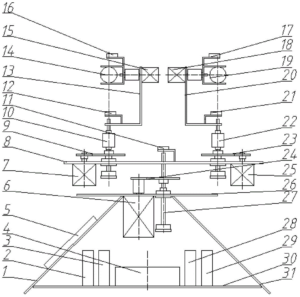
[0032] refer to figure 1 , the depth information extraction and profile analysis system of the binocular vision area target of the present invention comprises a left bracket 1, a right bracket 31, a first driver 2, a second driver 3, a third driver 4, a fourth driver 28, a fifth driver Driver 29, control board 5, first stepper motor 15, second stepper motor 7, third stepper motor 6, fourth stepper motor 25, fifth stepper motor 18, rotating plate 8, first transmission gear Group 9, second transmission gear set 23, third transmission gear set 24, left rotation shaft 10, right rotation shaft 22, main shaft electronic compass 11, left electronic compass 12, right electronic compass 21, left camera bracket 13, right camera bracket 20 , left camera 14, right camera 19, left electronic gyroscope 16, right electronic gyroscope 17, support plate 26, main shaft 27 and base plat...
PUM
Abstract
The invention discloses a binocular vision area target depth information extraction and cross section analysis system and method. The system comprises a left bracket, a right bracket, a first driver, a second driver, a third driver, a fourth driver, a fifth driver, a control panel, a first step motor, a second step motor, a third step motor, a fourth step motor, a fifth step motor, a rotating plate, a first transmission gear set, a second transmission gear set, a third transmission gear set, a left rotating shaft, a right rotating shaft, a main shaft electronic compass, a left electronic compass, a right electronic compass, a left camera bracket, a right camera bracket, a left camera, a right camera, a left electronic gyroscope, a right electronic gyroscope, a bracket plate, a bracket plate, a main shaft and a bottom plate, wherein the third transmission gear set consists of a first gear and a second gear; the first transmission gear set consists of a third gear and a fourth gear; the second transmission gear set consists of a fifth gear and a sixth gear. The binocular vision area target depth information extraction and cross section analysis system and method can be used for obtaining the cross section information on preset tracks in areas to be detected.
Description
technical field [0001] The invention belongs to the field of motion control, and relates to a system and method for extracting depth information and profile analysis of a target in a binocular vision area. Background technique [0002] At present, with the development of science and technology and the continuous progress of artificial intelligence, various intelligent vehicles that can walk autonomously have been applied in various fields, such as agricultural picking robots, outer space exploration robots, explosive disposal robots, etc. Their walking The road environment is often complex and is an unstructured road. In order to enable the intelligent mobile robot to walk in the complex road environment, it is necessary to obtain the environmental information of the road surface in advance: road surface roughness (protrusions and depressions of the road surface), slope information, etc. Only by fully obtaining the walking information of the road surface can the intelligent ...
Claims
Application Information
Patent Timeline
Application Date:The date an application was filed.
Publication Date:The date a patent or application was officially published.
First Publication Date:The earliest publication date of a patent with the same application number.
Issue Date:Publication date of the patent grant document.
PCT Entry Date:The Entry date of PCT National Phase.
Estimated Expiry Date:The statutory expiry date of a patent right according to the Patent Law, and it is the longest term of protection that the patent right can achieve without the termination of the patent right due to other reasons(Term extension factor has been taken into account ).
Invalid Date:Actual expiry date is based on effective date or publication date of legal transaction data of invalid patent.

