
Method and device for displaying wave-shaped dynamic image

A technology of dynamic images and display methods, applied in the field of communications, can solve the problems of monotonous animation types, a large number of Gif pictures, and resource consumption, and achieve the effect of reducing CPU computing pressure and memory consumption.

Inactive Publication Date: 2015-05-27
CHINA MOBILE COMM GRP CO LTD
View PDF4 Cites 7 Cited by
  • Summary
  • Abstract
  • Description
  • Claims
  • Application Information

AI Technical Summary

Problems solved by technology

[0004] In the above-mentioned Tween animation scheme, the supported animation types are monotonous, just simple rotation, fade in and fade out, etc., which cannot meet the user's experience requirements
In the above-mentioned Frame animation scheme, it consumes more resources and puts a lot of computing pressure on the CPU (Central Processing Unit, central processing unit), which will cause startup delays and other phenomena, and requires a large number of Gif images, which consumes more memory.

Method used


Image

  • Method and device for displaying wave-shaped dynamic image
  • Method and device for displaying wave-shaped dynamic image
  • Method and device for displaying wave-shaped dynamic image

Examples


Embodiment 1

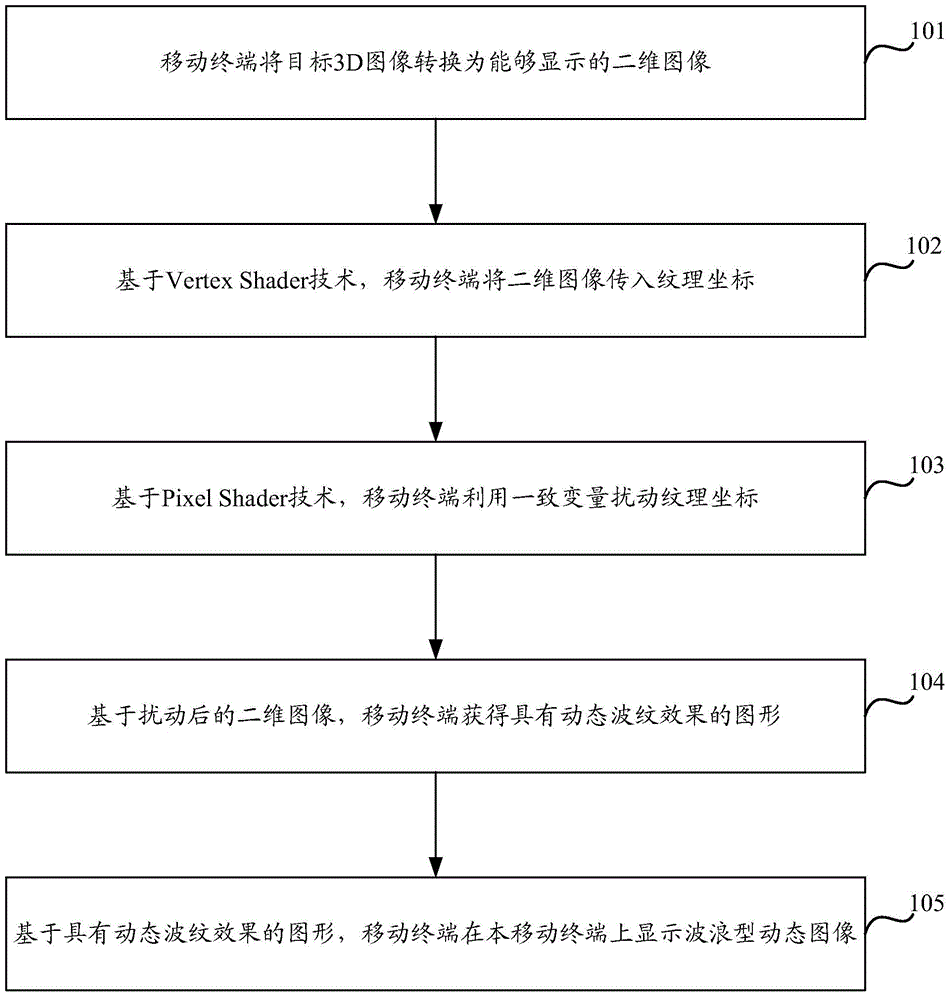
[0025] Aiming at the problems existing in the prior art, Embodiment 1 of the present invention provides a method for displaying wave-shaped dynamic images, such as figure 1 As shown, the display method of the wave-shaped dynamic image includes the following steps:

[0026] In step 101, the mobile terminal converts the target 3D image into a displayable two-dimensional image.

[0027] Among them, the target 3D image (that is, the wave-shaped dynamic image to be displayed finally) can be converted into a displayable two-dimensional image through a series of transformations, and the conversion process will not be described in detail here.

[0028] Step 102, based on the Vertex Shader technology, the mobile terminal transmits the two-dimensional image to the texture coordinates.

[0029] Among them, the texture is actually a two-dimensional array whose elements are some color values. A single color value is called a texture element or a texel. Each texel has a unique address in t...

Embodiment 2

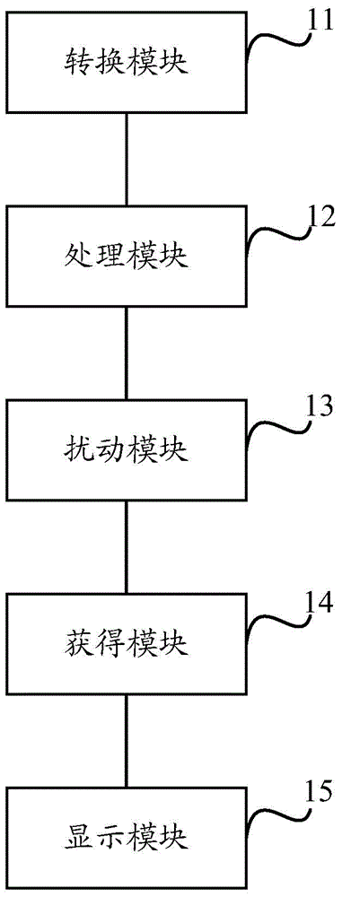
[0059] Based on the same inventive concept as the above method, a mobile terminal is also provided in the embodiment of the present invention, such as image 3 As shown, the mobile terminal specifically includes: a conversion module 11 for converting a target 3D image into a displayable two-dimensional image; a processing module 12 for passing the two-dimensional image into texture coordinates; a disturbance module 13 for using The texture coordinates are perturbed by consistent variables; the obtaining module 14 is used to obtain a graphic with a dynamic ripple effect based on the disturbed two-dimensional image; the display module 15 is used to obtain a graphic with a dynamic ripple effect based on the graphic with a dynamic ripple effect in the A wave-shaped dynamic image is displayed on the above-mentioned mobile terminal.

[0060] The perturbation module 13 is specifically configured to use the consistent variable to generate a sine function, and perturb the texture coord...


PUM


Abstract

The invention discloses method and device for displaying a wave-shaped dynamic image. The method comprises the steps of converting a target 3D image into a three-dimensional image which can be displayed through a mobile terminal; transmitting the two-dimensional image into a texture coordinate through the mobile terminal; disturbing the texture coordinate through the mobile terminal according to uniform variables; acquiring a graph with the dynamic wave effect by the mobile terminal according to the disturbed two-dimensional image; displaying the wave-shaped dynamic image through the mobile terminal according to the graph with the dynamic wave effect. According to the method, the Vertex Shader technology and the Pixel Shader technology are adopted to display the wave dynamic image in the mobile terminal, namely, the 3D dynamic wave effect can be achieved, the real dynamic wave effect can be rendered, the dynamic real-time rendering is achieved, the CPU operation pressure is relieved, and consumption of memory can be reduced.

Description

technical field [0001] The present invention relates to the communication field, in particular to a display method and device for a wave-shaped dynamic image. Background technique [0002] With the continuous development of mobile terminal technology, the user's requirements for the graphical interface of the mobile platform are also further improved. The ordinary two-dimensional interface can no longer meet the user experience requirements. Users begin to pursue a higher level of stereoscopic 3D effects. The emergence of stereoscopic 3D technology has also become a reality for mobile terminals, and more and more mobile terminals have used naked-eye 3D screens. Furthermore, after the mobile terminal supports a GPU (Graphic Processing Unit, graphics processing unit), real-time display of complex stereoscopic 3D scene images becomes possible. At present, users have been able to experience visually impactful animation effects such as three-dimensional page turning, fade in and...

Claims


Application Information

Patent Timeline
IPC IPC(8): G06F3/14
CPCG06F3/1407
Inventor 李宽
Owner CHINA MOBILE COMM GRP CO LTD
Learn More