
Positioning mechanism

A technology of positioning mechanism and cam mechanism, applied in workpiece clamping devices, manufacturing tools, etc., can solve the problems of high manufacturing cost, low production efficiency, inconvenient operation, etc., to save manufacturing cost and management cost, improve production efficiency, save money artificial effect

Active Publication Date: 2015-06-03
BOZHON PRECISION IND TECH CO LTD
View PDF7 Cites 5 Cited by
  • Summary
  • Abstract
  • Description
  • Claims
  • Application Information

AI Technical Summary

Problems solved by technology

[0002] At present, many enterprises generally process battery products in the form of an assembly line. The battery is usually placed in a positioning device with a storage slot for installation. After the installation is completed, the battery is taken out of the storage slot. Since the storage slot is quite small, Moreover, there is a relatively large resistance force between the remaining parts of the installed battery and the accommodating tank, and it is usually necessary to contact other auxiliary tools to remove the battery from the positioning device, which is inconvenient, time-consuming and laborious to operate, and the production efficiency is low. At the same time, the existing The positioning device cannot be used for different types and types of batteries, the application is limited, the manufacturing cost is high, and its positioning accuracy is low, which cannot meet the use of battery installation with high precision requirements

Method used


Image

  • Positioning mechanism
  • Positioning mechanism
  • Positioning mechanism

Examples


Embodiment

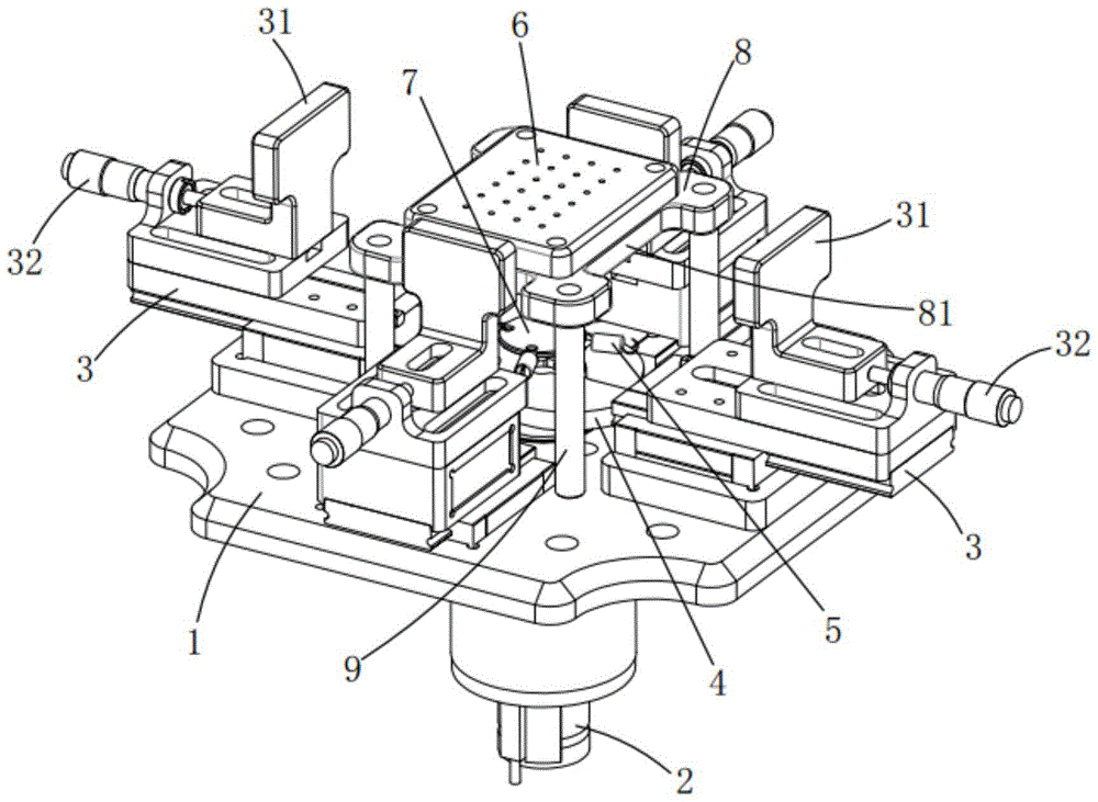
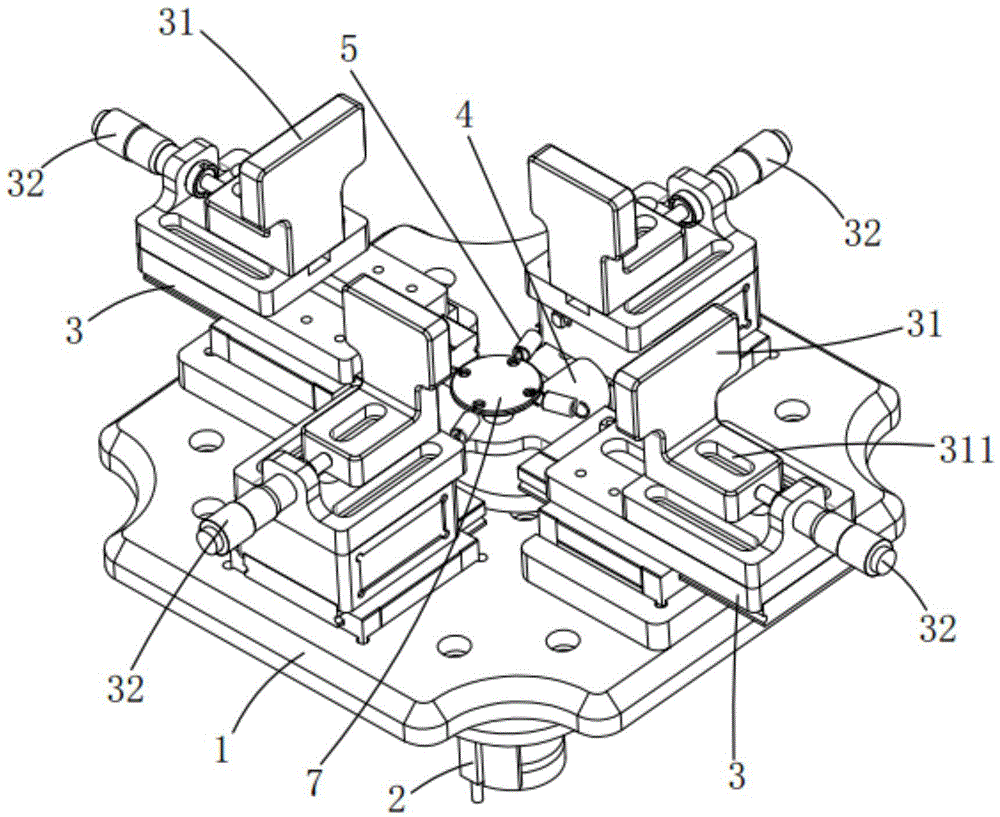
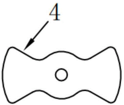
[0018] like figure 1 As shown, a positioning mechanism includes a base plate 1, a power source 2, a sliding module 3, a cam mechanism 4, a telescopic mechanism 5 and a carrying object 6. The base plate 1 is square, and each side of it is provided with a sliding module 3 Positioning push blocks 31 are respectively fixed on the sliding module 3, and a fine-tuning mechanism 32 is installed on its outer edge. , to increase the accuracy and reliability of object positioning; such as figure 2 As shown, the power source 2 is installed on the bottom of the base plate 1, the cam mechanism 4 is arranged in the middle of the base plate 1 and connected with the power source 2, a turntable 7 is fixed on the cam mechanism 4, and four telescopic mechanisms 5 are evenly arranged on the edge of the turntable 7 , each telescoping mechanism 5 is fixedly connected to the inner side of the corresponding sliding module 3; a bearing plate 8 is arranged directly above the turntable 7, and the four ...


PUM


Abstract

The invention relates to a positioning mechanism. The positioning mechanism comprises a bottom plate, a power source, slidable modules, a cam mechanism, retractable mechanisms and a bearing object, wherein the bottom plate is square, each side thereof is provided with a slidable module, and positioning push blocks are respectively arranged on the slidable modules; the power source is installed at the bottom portion of the bottom plate, the cam mechanism is arranged at the middle portion of the bottom plate and is connected with the power source, a turntable is arranged on the cam mechanism, four retractable mechanisms are uniformly arranged on the edge of the turntable, and each retractable mechanism is fixedly connected with the corresponding slidable module; a bearing plate is arranged above the turntable, the four corners of the bearing plate are respectively fixed on the bottom plate through stand columns, and the bearing object for placing an object is arranged on the bearing plate. By driving the cam mechanism to rotate through the power source to simultaneously and accurately position the four sides of the object placed in the bearing object, high-accuracy quick positioning of various products can be realized, the time, labor and manpower are saved, the production efficiency is improved and the manufacturing cost and management cost are greatly reduced.

Description

Technical field: [0001] The invention relates to the technical field of product positioning, and more specifically relates to a high-precision fast positioning mechanism. Background technique: [0002] At present, many companies generally process battery products in an assembly line. The battery is usually placed in a positioning device with a storage tank for installation. After the installation is completed, the battery is taken out of the storage tank. Since the storage tank is quite small, Moreover, there is a relatively large resistance force between the remaining parts of the installed battery and the accommodating tank, and it is usually necessary to contact other auxiliary tools to remove the battery from the positioning device, which is inconvenient, time-consuming and laborious to operate, and the production efficiency is low. At the same time, the existing The positioning device of the present invention cannot be used for different types and types of batteries, ha...

Claims


Application Information

Patent Timeline
Patent Type & Authority Applications(China)
IPC IPC(8): B25B11/00
CPCB25B11/00
Inventor 吕绍林杨愉强王建福刘陈亮
Owner BOZHON PRECISION IND TECH CO LTD
Learn More