Wire coiling and uncoiling device

A technology of a take-up and pay-off device and a wire roller, which is applied in the field of take-up and pay-off devices, can solve the problems of time-consuming and laborious manual wire take-up, no automatic wire take-up function, and the released wires are easy to be scattered and entangled together, so as to achieve convenient use. Effect

Inactive Publication Date: 2015-06-03
QINGDAO YONGTONG ELEVATOR ENG
View PDF7 Cites 4 Cited by
  • Summary
  • Abstract
  • Description
  • Claims
  • Application Information

AI Technical Summary

Problems solved by technology

[0002] In industrial production, it is often necessary to use fixed wire rollers, but most of the existing wire rollers do not have the function of automatic wire take-up. Manual wire take-up is time-consuming and laborious, and the released wires are easily scattered and entangled together.

Method used


Image

  • Wire coiling and uncoiling device

Examples


Embodiment Construction

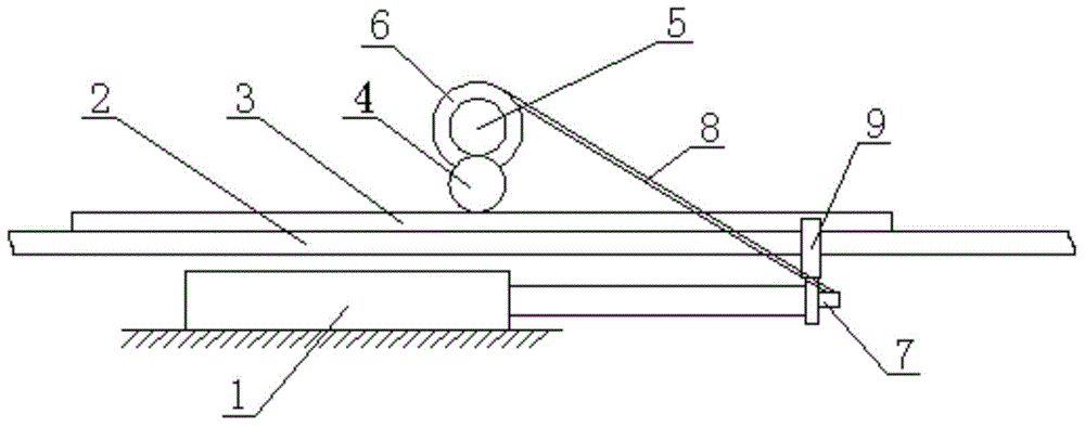
[0008] The present invention will be further explained below in conjunction with the drawings and examples:

[0009] Such as figure 1 As shown, a wire take-up and pay-off device of this embodiment includes: a translation mechanism 1, a guide rail 2, a rack 3, a first spur gear 4, a second spur gear 5, a wire roller 6 and a chuck 7. A wire 8 is wound on the roller 6, and the chuck 7 is fixedly connected to the movable part of the translation mechanism 1 and clamps a free end of the wire 8. The movable part of the translation mechanism 1 is connected to the rack through a connecting piece 9 3-phase fixed connection, the rack 3 is placed on the guide rail 2 and slidably connected to the guide rail 2, the rack 3 meshes with the first spur gear 4, and the first spur gear 4 is in phase with the second spur gear 5. When meshing, the second spur gear 5 is coaxially fixed to the line roller 6.

[0010] Preferably, the translation mechanism 1 is an air cylinder or a trolley.

[0011] The pr...


PUM


Abstract

The invention relates to an industrial device, and in particular relates to a wire coiling and uncoiling device. The device comprises a translation mechanism, a guide rail, a rack, a first straight gear, a second straight gear, a wire roller and a chuck; the wire roller is coiled with a conductor; the chuck is fixedly connected to a movable part of the translation mechanism and clamps a free end of the conductor; the movable part of the translation mechanism is fixedly connected with the rack through a connecting part; the rack is positioned on the guide rail to be glidingly connected with the guide rail, wherein the rack engages with the first straight gear which engages with a second straight gear; the second straight gear is coaxially fixedly connected with the wire roller. The device is convenient to use, and automatic to coil and uncoil a wire as the translation mechanism runs, so that the wire can be avoided disordering, and manual coiling and uncoiling is saved.

Description

Technical field [0001] The invention relates to an industrial device, in particular to a retractable wire device. Background technique [0002] It is often necessary to use fixed wire rollers in industrial production, but most of the existing wire rollers do not have the function of automatic winding up. Manual winding up is time-consuming and laborious, and the discharged threads are easily scattered and entangled together. Summary of the invention [0003] The present invention aims to solve the above problems and provides a take-up and pay-off device, which is convenient to use, can automatically take-up and pay-off with the operation of the translation mechanism, the line will not be scattered, and there is no need to manually take-up and pay off. The technical solution adopted is as follows: [0004] A wire take-up and pay-off device, comprising: a translation mechanism, a guide rail, a rack, a first spur gear, a second spur gear, a wire roller and a chuck, the wire roller is ...

Claims


Application Information

Patent Timeline
Patent Type & Authority Applications(China)
IPC IPC(8): B65H75/42B65H75/44
Inventor 杨光代立超
Owner QINGDAO YONGTONG ELEVATOR ENG
Why Eureka
Try Eureka