Chemical fiber drying mechanism

A chemical fiber drying technology, applied in progressive dryers, dryers, drying solid materials, etc., can solve problems such as affecting drying efficiency, uneven heating of chemical fiber, and scattering, and achieve the effect of ensuring drying efficiency.

Inactive Publication Date: 2015-11-25
CHENGDU JIAMEIJIA SCI & TECH
View PDF7 Cites 3 Cited by
  • Summary
  • Abstract
  • Description
  • Claims
  • Application Information

AI Technical Summary

Problems solved by technology

[0002] In the process of manufacturing and processing chemical fiber products, it is often necessary to use a chemical fiber drying mechanism to dry the chemical fiber, but for the existing chemical fiber drying mechanism, the heat source is often only distributed in the same direction or in a certain direction , so that the heating of the chemical fiber filaments placed on the conveyor belt is not uniform. At the same time, the wind direction of the hot air in the drying mechanism cannot effectively form a hot air circulation, which greatly affects the drying efficiency. In addition, during the drying process of the chemical fiber filaments, the original neat The discharged chemical fibers will also become scattered due to conveyor belt transmission and wind heating, and even the chemical fibers are entangled with each other, which greatly affects the drying efficiency, drying effect and subsequent processing procedures of chemical fibers

Method used


Image

  • Chemical fiber drying mechanism
  • Chemical fiber drying mechanism
  • Chemical fiber drying mechanism

Examples


Embodiment Construction

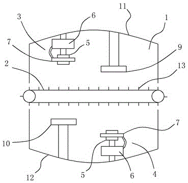
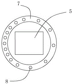
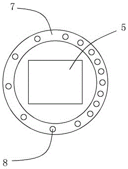
[0013] Such as Figure 1 to Figure 3 As shown, a chemical fiber drying mechanism includes a drying chamber 1 and a conveyor belt 2 located in the middle of the drying chamber 1, wherein a first combined heating device 3 and a second combined heating device 3 are respectively arranged on the upper left side and the lower right side of the drying chamber 1. Combined heating device 4, the first combined heating device 3 and the second combined heating device 4 all include a metal heating block 5, a hot air blower 6 and an annular air duct 7 communicating with the hot blower 6, and the first combined heating device 3 Hot air blower 6 is arranged on the top of the metal heating block 5 of the first combined heating device 3, and the hot air blower 6 of the second combined heating device 4 is arranged under the metal heating block 5 of the second combined heating device 4, and the first combined heating device 3 and the annular air duct 7 of the second combined heating device 4 all ...


PUM


Abstract

The invention relates to a chemical fiber drying mechanism which comprises a drying chamber, a conveying belt, a first combined heating device and a second combined heating device. The bottom of an annular air pipe of the first combined heating device and the top of an annular air pipe of the second combined heating device are each provided with a plurality of air outlet holes. A first metal heating plate and a second metal heating plate are arranged on the right side of the upper portion of the drying chamber and the left side of the lower portion of the drying chamber respectively. The top wall of the drying chamber is an arc-shaped wall protruding upwards, and the bottom wall of the drying chamber is an arc-shaped wall protruding downwards. The height of the first metal heating plate is smaller than that of the first combined heating device, and the height of the second metal heating plate is smaller than that of the second combined heating device. The conveying belt is of a metal net structure, and a plurality of limiting rods are arranged on the metal net. According to the structure, it can be guaranteed that chemical fibers are evenly heated in the drying process, hot air circulation is effectively formed, and meanwhile the chemical fibers cannot be scattered or wound.

Description

technical field [0001] The invention relates to a chemical fiber drying mechanism. Background technique [0002] In the process of manufacturing and processing chemical fiber products, it is often necessary to use a chemical fiber drying mechanism to dry the chemical fiber, but for the existing chemical fiber drying mechanism, the heat source is often only distributed in the same direction or in a certain direction , so that the heating of the chemical fiber filaments placed on the conveyor belt is not uniform. At the same time, the wind direction of the hot air in the drying mechanism cannot effectively form a hot air circulation, which greatly affects the drying efficiency. In addition, during the drying process of the chemical fiber filaments, the original neat The discharged chemical fiber filaments will also become scattered due to conveyor belt transmission and wind blowing heating, and even the chemical fiber filaments are entangled with each other, which greatly affe...

Claims


Application Information

Patent Timeline
Patent Type & Authority Applications(China)
IPC IPC(8): F26B13/02F26B21/00F26B23/00F26B25/00
Inventor 梁枫
Owner CHENGDU JIAMEIJIA SCI & TECH
Why Eureka
Try Eureka