A kind of support angle steel and iron tower rest platform
A technology of angle steel and iron tower, which is applied in the field of supporting angle steel and iron tower rest platform, can solve the problems of limited load-bearing capacity of the rest platform and cannot adapt to the increasing requirements of the load-bearing capacity of the rest platform, and achieves the effect of obvious technical advantages
- Summary
- Abstract
- Description
- Claims
- Application Information
AI Technical Summary
Problems solved by technology
Method used
Image


Examples
Embodiment 1
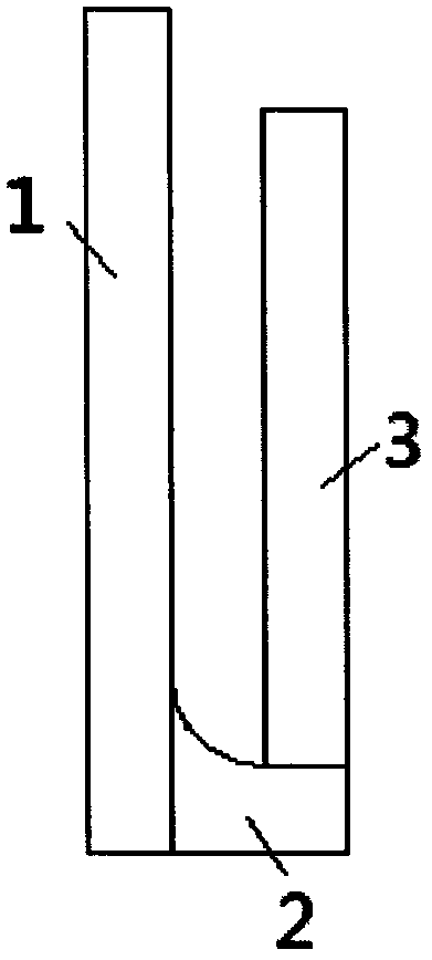
[0045] See image 3 and Figure 5 , a support angle steel, comprising a support angle steel body 5 and support angle steel connection ends 6 located at both ends of the support angle steel body, the support angle steel body 5 includes a bending surface, a support surface 1 constituting a load-bearing surface, and a connection bending surface and a support surface 1 angle steel edge, the bending surface is the first bending section 2 and the second bending section 3 from one side to the other side of the angle steel edge, and the distance between the first bending section and the second bending section is 90 ° angle. The skilled person can manufacture the supporting angle steel described in this embodiment by using the corresponding angle steel as a raw material with reference to the content of the specific embodiment.
Embodiment 2-10
[0047] The supporting angles described in Examples 2-10 are basically the same as those in Example 1, except that Example 1 does not specify the specific values of the first bending section, the second bending section, and the thickness of the supporting angles, while Example 2 The supporting angle steel in -10 lists the specific values of the first bending section, the second bending section and the thickness. Table 3 shows that the first bending section, the second bending section and the thickness of the embodiment 2-10 are different. In this case, the comparison table of the supporting force of the unprocessed flat steel of the same type.
[0048] table 3
[0049]
Embodiment 11
[0051] See Figure 4 and Figure 6 , a support angle steel, comprising a support angle steel body 22 and support angle steel connection ends 21 located at both ends of the support angle steel body, the support angle steel body 22 includes a bending surface, a supporting surface 11 constituting a load-bearing surface, and connecting the bending surface and the supporting surface 11 angle steel edge, the bending surface from one side of the angle steel edge to the other side is the first bending section 12, the second bending section 13 and the third bending section 14, the first bending section 12 and the second bending section The angle between the second bending section 13 and the second bending section 13 and the third bending section 14 is 90°. The skilled person can manufacture the supporting angle steel described in this embodiment by using the corresponding angle steel as a raw material with reference to the content of the specific embodiment.
PUM
 Abstract
Description
Claims
Application Information
 - R&D
- Intellectual Property
- Life Sciences
- Materials
- Tech Scout
- Unparalleled Data Quality
- Higher Quality Content
- 60% Fewer Hallucinations
Browse by: Latest US Patents, China's latest patents, Technical Efficacy Thesaurus, Application Domain, Technology Topic, Popular Technical Reports.
© 2025 PatSnap. All rights reserved.Legal|Privacy policy|Modern Slavery Act Transparency Statement|Sitemap|About US| Contact US: help@patsnap.com