LED mining lamp radiator

A technology of LED high bay lamp and radiator, which is applied in lighting and heating equipment, cooling/heating device of lighting device, lighting device, etc., can solve the problems of attenuation affecting the life of LED lamps, general heat dissipation effect of radiator, general heat dissipation effect, etc. , to achieve the effect of good heat dissipation, conducive to heat dissipation and protection of the radiator

Inactive Publication Date: 2015-06-03
SUZHOU CHENGYUAN PHOTOELECTRIC TECH
View PDF7 Cites 0 Cited by
  • Summary
  • Abstract
  • Description
  • Claims
  • Application Information

AI Technical Summary

Problems solved by technology

[0002] The application of ultra-high-brightness LED lamps in the LED lighting industry continues to expand, especially LED high bay lamps. It will accelerate the attenuation and seriously affect the life of LED lamps. The heat dissipation effect of traditional design LED high bay light radiators is average. For example, the document with the Chinese application number 201120525095.0 discloses a LED high bay light radiator, including heat storage aluminum columns, aluminum mounting plates and heat dissipation The outer circle of the thermal storage aluminum column is provided with a plurality of trapezoidal grooves, which are the grooves of the aluminum column. The heat sink is inserted into the groove of the aluminum column by the elastic deformation of the material, and the aluminum mounting plate is tightly connected to the thermal storage aluminum column. Fixed connection, combined into a LED high bay lamp radiator, although this design is beautiful in appearance and light in weight, but the design is too complicated, and there is no small fan, the heat dissipation effect is average, the invention solves the above disadvantages

Method used


Image

  • LED mining lamp radiator
  • LED mining lamp radiator

Examples


Embodiment Construction

[0013] In order to make the technical means, creative features, goals and effects achieved by the present invention easy to understand, the present invention will be further described below in conjunction with specific embodiments.

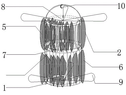
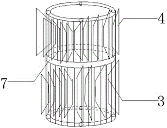
[0014] Such as figure 1 with figure 2 As shown, a heat sink for LED industrial and mining lamps includes a hollow shaft 1 and a heat sink 2, the hollow shaft 1 is provided with a groove 3, the groove 3 is provided with a supporting piece 4, and the heat sink 2 and the The supporting sheet 3 is connected, and the heat sink 2 includes an upper heat sink 5 and a lower heat sink 6, and a heat insulating sheet 7 is arranged between the upper heat sink 5 and the lower heat sink 6, and the heat sink 2 is fan-shaped. The distance between the heat sinks 2 is 0.3-0.5 cm, and the top and bottom of the hollow shaft 1 are equipped with small fans 8. The fan-shaped heat sink is divided into upper and lower layers, and a partition is arranged in the middle to...


PUM

PropertyMeasurementUnit
Thicknessaaaaaaaaaa

Abstract

The invention discloses an LED mining lamp radiator, and relates to the field of LED lamp radiators. The LED mining lamp radiator comprises a hollow shaft and cooling fins, the hollow shaft is provided with grooves, supporting pieces are arranged in the grooves, the cooling fins are connected with the supporting pieces and comprise upper layer cooling fins and lower layer cooling fins, a heat insulation piece is arranged between the upper layer cooling fins and the lower layer cooling fins, the cooling fins are fan-shaped, the distances between the cooling fins are 0.3-0.5cm, and small fans are arranged at the top end and the bottom end of the hollow shaft. The fan-shaped cooling fins are divided into an upper layer and a lower layer, a partition plate is arranged between the upper layer and the lower layer, so that heat circulation is facilitated, heat dissipation is accelerated, efficiency is improved, the distances between the cooling fins are 0.3-0.5cm and are favorable for achieving the heat dissipation effect on the basis of fully utilizing space in addition, and meanwhile the small fans are arranged at the top end and the bottom end of the hollow shaft, thus being favorable for air flowing, and achieving better heat dissipation effect; compared with the design on the market, the design is more favorable for protecting an LED mining lamp, and the service life of the LED mining lamp is prolonged.

Description

technical field [0001] The invention relates to the field of radiators for LED lamps, in particular to a radiator for LED industrial and mining lamps. Background technique [0002] The application of ultra-high-brightness LED lamps in the LED lighting industry continues to expand, especially LED high bay lamps. It will accelerate the attenuation and seriously affect the life of LED lamps. The heat dissipation effect of traditional design LED high bay light radiators is average. For example, the document with the Chinese application number 201120525095.0 discloses a LED high bay light radiator, including heat storage aluminum columns, aluminum mounting plates and heat dissipation The outer circle of the thermal storage aluminum column is provided with a plurality of trapezoidal grooves, which are the grooves of the aluminum column. The heat sink is inserted into the groove of the aluminum column by the elastic deformation of the material, and the aluminum mounting plate is ti...

Claims


Application Information

Patent Timeline
IPC IPC(8): F21V29/67F21V29/77F21W131/402F21Y101/02
CPCF21S2/00F21W2131/402F21Y2101/00
Inventor 戴岳平
Owner SUZHOU CHENGYUAN PHOTOELECTRIC TECH
Why Eureka
Try Eureka