

Radiating device and method and cabinet
A technology of heat dissipation device and heat dissipation method, which is applied in cooling/ventilation/heating transformation, electrical equipment shell/cabinet/drawer, electrical components, etc., to solve the problem of heat dissipation power consumption and effect, and improve the effect of heat dissipation
- Summary
- Abstract
- Description
- Claims
- Application Information
AI Technical Summary
Problems solved by technology
Method used
Image

Examples
Embodiment 1
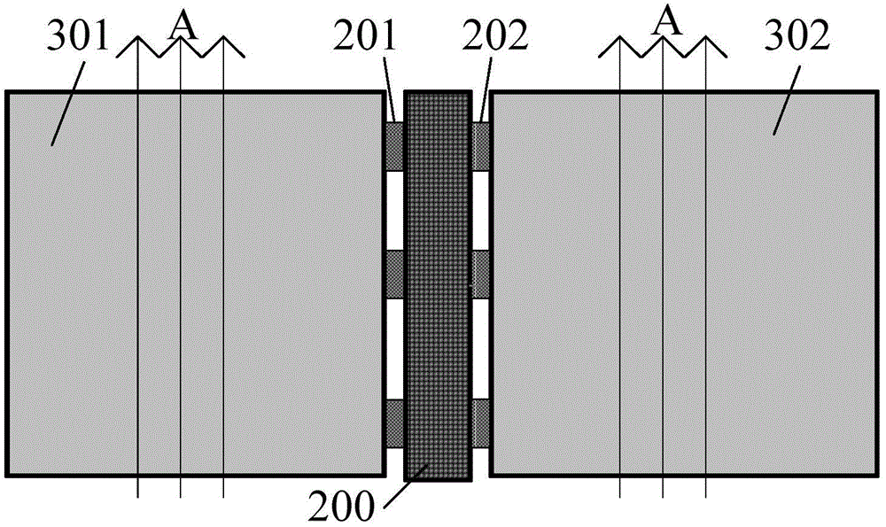
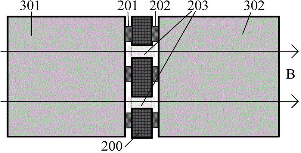
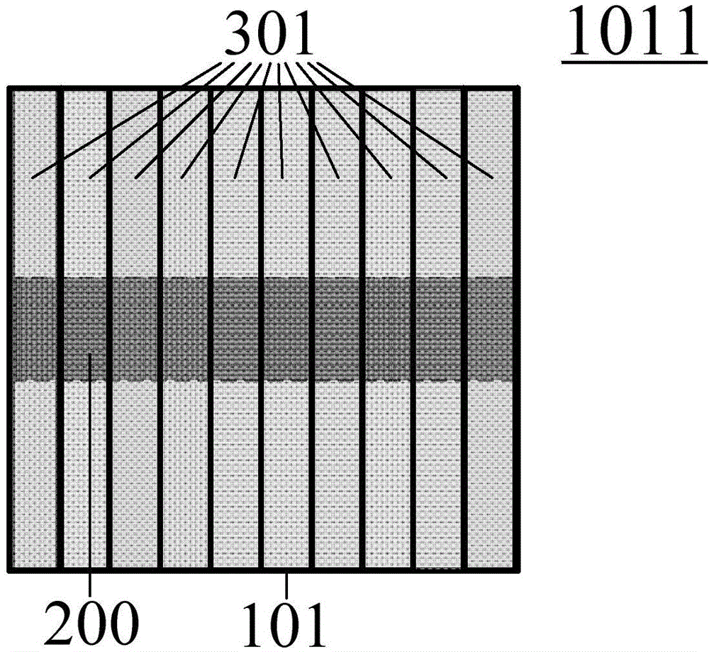
[0035] The cold air is inhaled from the front panel 1011 of the subrack and drawn out from the rear panel 1012 of the subrack. The front plug-in board 301 and the rear plug-in board 302 are connected to the backplane 200 through connectors. The design of the backplane 200 is different from the traditional backplane design. The width of the backplane is very narrow to maximize the airflow channel of the main air duct. The heat of the front-plug single board 301 can be drawn out quickly, which facilitates the heat dissipation of the machine frame.
[0036] attached Figures 3a to 3d It is a specific embodiment of the present invention.
[0037] Such as Figure 3a As shown, the front plug-in board 301 and the rear plug-in board 302 are placed in parallel inside the subrack 101 . attached Figure 3b As shown, the rear boards 302 are respectively located on the left and right sides of the subrack 101, and the fan unit 501 is located in the middle of the rear panel 1012 of the ...
Embodiment 2
[0041] attached Figures 4a-4d It is a specific embodiment of the present invention.
[0042] attached Figure 4a , 4b As shown, the front plug-in board 301 and the rear plug-in board 302 are vertically placed inside the subrack 101 , and the backplane 200 is placed at the lower part of the subrack 101 and is close to the lower surface of the subrack 101 . The slot direction of the rear board 302 is parallel to the direction of the horizontal panel of the subrack.
[0043] attached Figure 4c with 4dAs shown, the cold air is inhaled from the air inlet 701 on the panel of the front board 301 , and is directly drawn out by the fan unit 501 after passing through the front board 301 . The rear board windshield 122 and the box panel form the rear board heat dissipation air duct. The air inlet 601 is located at the bottom of the sub-box 101 ; the air inlet 611 is located on the left and right sides of the sub-box 101 , and is scattered on the upper and lower sides of the circu...
Embodiment 3
[0045] attached Figure 5a with 5b It is a specific embodiment of the present invention. Compared with the second embodiment, the difference is that the circuit board 312 of the rear-inserted single board 302 is retracted inwardly, and the cold air inhaled by the air inlet of 601 can enter the mixed air area 102 through the upper and lower surfaces of the circuit board 312 respectively, and then the air is blown by the fan. The unit 501 extracts hot air to improve the heat dissipation effect of the rear plug-in board 302 .
PUM
 Abstract
Description
Claims
Application Information