
Magnetomotive light-emitting toy jumping ball

A technology for toys and spheres, used in toys, sports accessories, entertainment, etc., can solve the problems of broken, broken skin, and single lighting form of lighting-related electronic control components, so as to increase playability and speed up heat dissipation. Effect

Active Publication Date: 2020-01-10
日照市睿尔泽新材料科技有限公司
View PDF5 Cites 4 Cited by
  • Summary
  • Abstract
  • Description
  • Claims
  • Application Information

AI Technical Summary

Problems solved by technology

[0003] However, after the jumping ball is used for a period of time, especially in summer, the calf is exposed. Due to the long-term friction between the force-generating part of the calf and the collar, the temperature of the force-generating part will increase, and the continuously rotating collar will always When in contact with the user's calf, the heat cannot be dissipated quickly, causing the user to feel uncomfortable, and even causing the user's skin to be red, swollen and broken. In order to increase the fun of the existing bouncing ball, light is usually set in the toy Colored lights are used to attract children. The electronically controlled light-emitting color lights have a single light-emitting form, and the lighting-related electronic control components are easily broken during play, and the service life is short. When the light-emitting color lights no longer glow, the toy is no longer Re-attract children, easy to be abandoned by children

Method used


Image

  • Magnetomotive light-emitting toy jumping ball
  • Magnetomotive light-emitting toy jumping ball

Examples


Embodiment Construction

[0016] In order to make the above objects, features and advantages of the present invention more comprehensible, specific implementations of the present invention will be described in detail below in conjunction with the accompanying drawings. In the following description, numerous specific details are set forth in order to provide a thorough understanding of the present invention. However, the present invention can be implemented in many other ways different from those described here, and those skilled in the art can make similar improvements without departing from the connotation of the present invention, so the present invention is not limited by the specific implementations disclosed below.

[0017] It should be noted that when an element is referred to as being “fixed” to another element, it can be directly on the other element or there can also be an intervening element. When an element is referred to as being "connected to" another element, it can be directly connected ...


PUM


Abstract

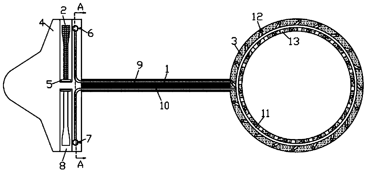
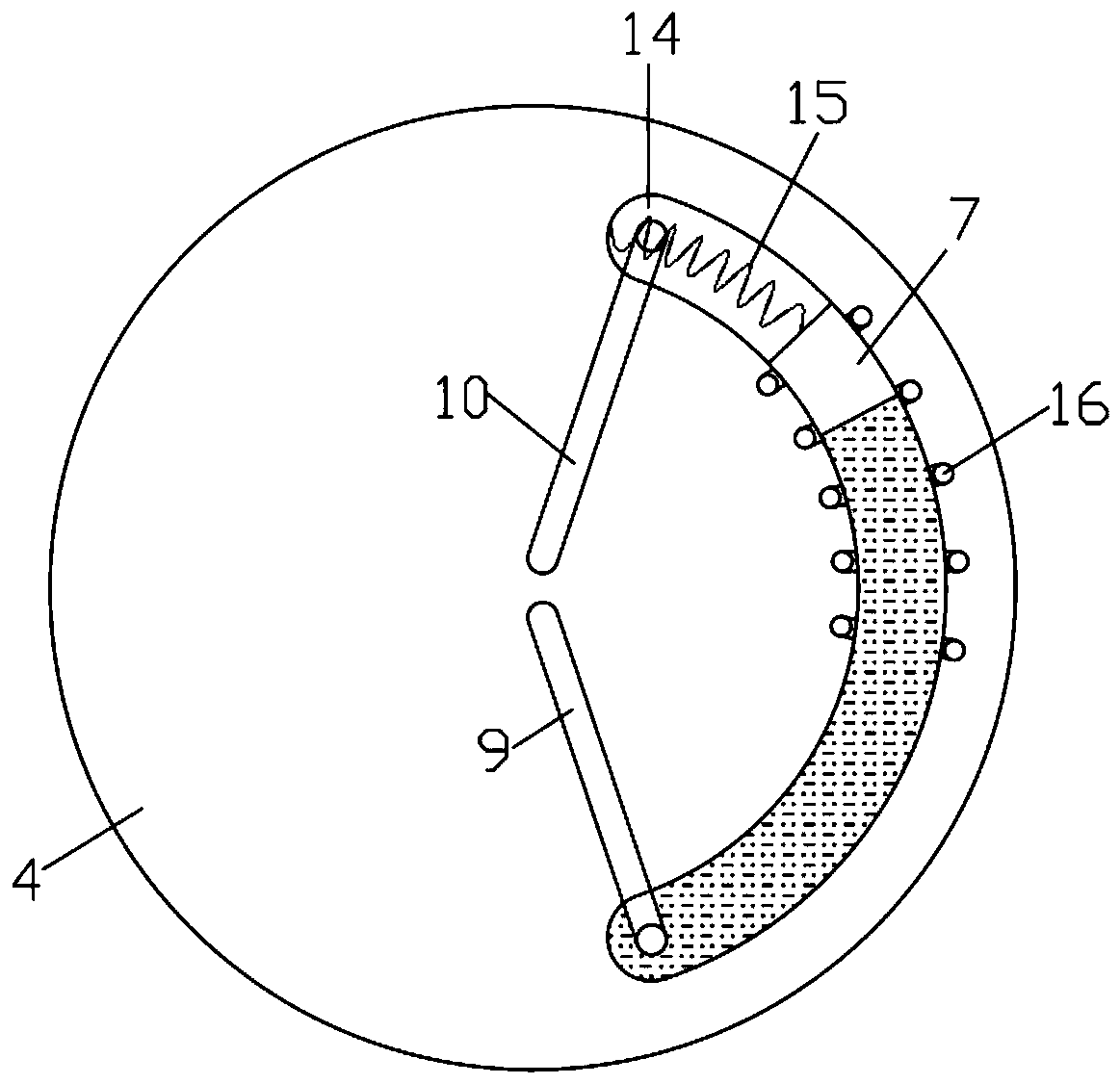
The invention discloses a magnetomotive light-emitting toy jumping ball. The magnetomotive light-emitting toy jumping ball comprises a sleeve ring and a ball body fixedly connected to the side wall ofthe sleeve ring through a connecting rod, wherein an annular groove is formed in the side wall of the ball body, a rotating sleeve is mounted at the inner side of the annular groove, blades are welded to the rotating sleeve at equal intervals, one of the blades is made of a magnetic material, and an arc-shaped cavity is formed in the side wall of the ball body. The blades rotate uninterruptedly,a magnetic block moves in the arc-shaped cavity in a reciprocating manner, during the uninterrupted moving process of the magnetic block, air in the arc-shaped cavity enters an annular cavity throughan air guide cavity and then is sprayed out from air outlet holes, and then heat dissipation is carried out on the leg and the sleeve ring; cooling liquid in the arc-shaped cavity is pressed into a spiral condensing cavity through a liquid guide cavity, and then the heat dissipation of the sleeve ring is accelerated; and during the process that the magnetic block moves in the arc-shaped cavity, induction current is formed in a spiral coil by utilizing the principle that the magnetic block cuts magnetic induction lines, further, a color lamp group emits light, and therefore, the playability ofthe jumping ball is increased.

Description

technical field [0001] The invention relates to the technical field of toys, in particular to a magnetic light-emitting toy bouncing ball. Background technique [0002] Jumping ball is a kind of toy suitable for children and adults. It consists of a ring on the calf and a sphere fixedly connected to the side wall of the ring through a connecting rod. The user puts the ring on the calf , By swinging the calf, the ball rotates along the axis of the ring, and the other leg avoids the ball to complete the play, so as to achieve the effect of weight loss and fitness, and can train children's coordination and reaction ability. [0003] However, after the jumping ball is used for a period of time, especially in summer, the calf is exposed. Due to the long-term friction between the force-generating part of the calf and the collar, the temperature of the force-generating part will increase, and the continuously rotating collar will always When in contact with the user's calf, the he...

Claims


Application Information

Patent Timeline
IPC IPC(8): A63B22/18A63H33/26A63H33/22
CPCA63B22/18A63B2022/185A63H33/22A63H33/26
Inventor 陈丹
Owner 日照市睿尔泽新材料科技有限公司
Learn More