an air conditioning system

An air-conditioning system and air-collecting pipe technology, which is applied in compressors, refrigeration components, refrigerators, etc., can solve the problems of affecting the performance of the unit, the accumulation of refrigeration oil, and the failure of refrigerant gas to pass through the heat exchange tubes, so as to achieve uniform gas distribution and improve reliability. performance, to ensure the effect of heat transfer performance

An air-conditioning system and air-collecting pipe technology, which is applied in compressors, refrigeration components, refrigerators, etc., can solve the problems of affecting the performance of the unit, the accumulation of refrigeration oil, and the failure of refrigerant gas to pass through the heat exchange tubes, so as to achieve uniform gas distribution and improve reliability. performance, to ensure the effect of heat transfer performance

CN104676973BActive Publication Date: 2017-12-29GREE ELECTRIC APPLIANCES INC

Image

  • an air conditioning system
  • an air conditioning system
  • an air conditioning system

Examples


Embodiment 1

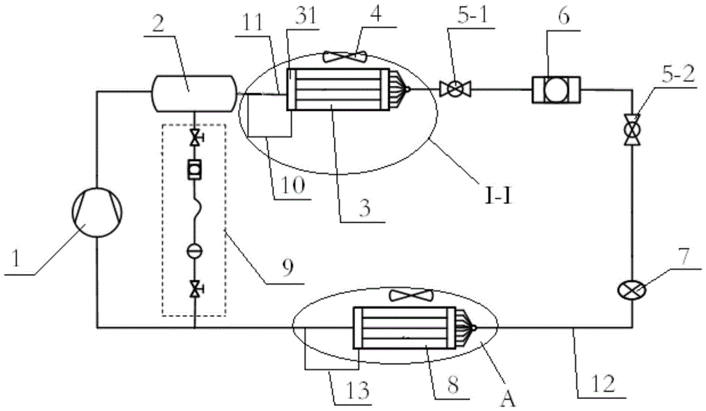
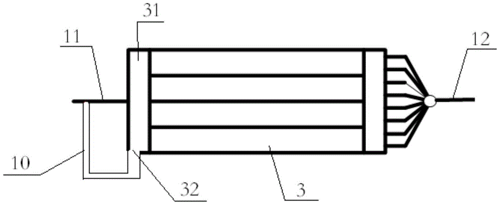
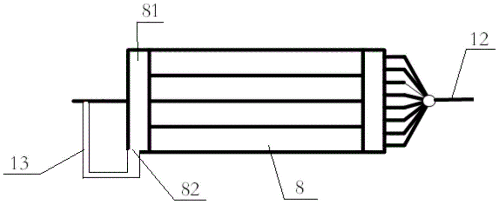
[0038] Such as Figure 1 to Figure 3 As shown, the air conditioning system provided by the present application includes a compressor 1 , an oil separator 2 , a first heat exchanger 3 , a second heat exchanger 8 and a third oil return pipeline 9 . The first heat exchanger 3 is arranged in the indoor unit of the air conditioning unit. The exhaust port of the compressor 1 is connected to the inlet of the oil separator 2 , and the oil outlet of the oil separator 2 is connected to the suction port of the compressor 1 through the third oil return pipeline 9 . One end of the second heat exchanger 8 is connected to the outlet end of the first heat exchanger 3 , and the other end is connected to the suction port of the compressor 1 . Wherein, the inlet end of the first heat exchanger 3 is provided with a first air collecting pipe 31, and several heat exchange pipes are arranged in the first heat exchanger 3, and the first air collecting pipe 31 is connected with the first air collecti...

Embodiment 2

[0057] Such as Figure 4 As shown, the difference between the air-conditioning system provided in this embodiment and the air-conditioning system provided in Embodiment 1 is that the other end of the first oil return pipeline 10 communicates with the third oil return pipeline 9 . In this solution, since the refrigerated oil retained in the first heat exchanger 3 does not need to pass through the oil separator 2, it returns directly to the third oil return line 9, and then returns to the compressor 1, reducing the amount of residual oil returning to the oil separator again. 2, so this solution has better beneficial effects than the solution provided by Example 1.

[0058] Apart from this, this embodiment is the same as the specific embodiment, and will not be repeated here.

Embodiment 3

[0060] Such as Figure 5 As shown, the difference between the air-conditioning system provided in this embodiment and the air-conditioning system provided in Embodiment 1 is that the other end of the first oil return pipeline 10 communicates with the suction port of the compressor 1 . In this scheme, since the refrigerated oil retained in the first heat exchanger 3 does not need to pass through the oil separator 2 and directly returns to the compressor 1, the trouble caused by the residual oil returning to the oil separator 2 is reduced, so This solution has better beneficial effects than the solution provided by Example 1.

[0061] Apart from this, this embodiment is the same as the specific embodiment, and will not be repeated here.


PUM


Abstract

The invention relates to the field of air conditioning, in particular to an air conditioning system. The air conditioning system comprises a compressor, a first heat exchanger and a second heat exchanger, wherein one end of the second heat exchanger is connected with the outlet end of the first heat exchanger, the other end of the second heat exchanger is communicated with the air suction port of the compressor, the inlet end of the first heat exchanger is provided with a first air collection pipe, the first air collection pipe is communicated with a heat exchange pipe in the first heat exchanger, the end, connected with the air suction port of the compressor, of the second heat exchanger is provided with a second air collection pipe, the lower end of the first air collection pipe and / or the second air collection pipe is provided with an oil return hole, the oil return hole of the first air collection pipe is connected with a first oil return pipeline and / or the oil return hole of the second air collection pipe is connected with a second oil return pipeline, the first oil return pipeline is used for recovering oil in the first gas collection pipe and / or the second oil return pipeline is used for recovering oil in the second gas collection pipe. The reliability of a unit is improved.

Description

technical field [0001] The invention relates to the field of air conditioning, in particular to an air conditioning system. Background technique [0002] Existing air-conditioning systems generally include finned heat exchangers, compressors and oil separators. Lubricating oil is very important to the normal operation of the compressor. It is necessary to ensure that there is sufficient lubricating oil in the compressor at any time during the operation of the air conditioner. . [0003] When the compressor is working, it will discharge high-temperature and high-pressure gas with lubricating oil from the gas outlet. The oil separator is used to separate the lubricating oil from the gas discharged from the gas outlet of the compressor and send it back to the compressor through the oil return pipeline. The gas from the lubricating oil then enters the finned heat exchanger for heat exchange. [0004] However, in the actual operation process, the oil separator cannot separate t...

Claims


Application Information

Patent Timeline
29 Dec 2017
Publication
CN104676973B
IPC
F25B31/00
CPC
F25B31/004
Inventors
ι’Ÿζ΅·ηŽ²; 程琦