Eureka AIR delivers breakthrough ideas for toughest innovation challenges, trusted by R&D personnel around the world.

A real-time optical power monitoring device

A technology of real-time monitoring and optical power, which is applied in the field of electric power, can solve problems such as low efficiency of fault elimination, inability to real-time monitor optical power of receiving and receiving devices, protection refusal to operate, etc., to achieve the effect of reducing personnel dispatch and shortening the time of fault elimination

Active Publication Date: 2017-07-18
STATE GRID CORP OF CHINA +1
View PDF6 Cites 0 Cited by
  • Summary
  • Abstract
  • Description
  • Claims
  • Application Information

AI Technical Summary

Problems solved by technology

When the optical fiber longitudinal difference protection device cannot receive the optical signal or the power of the received optical signal is too low, the optical fiber longitudinal difference protection device will send out an alarm signal and perform blocking protection to form a protection refusal in the fault state
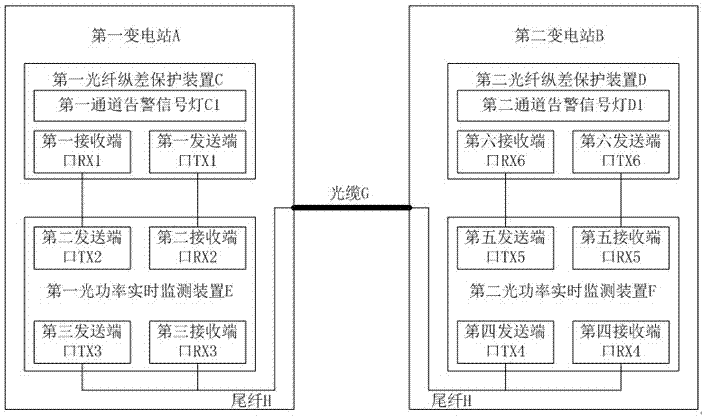
Under the above circumstances, the existing optical fiber differential protection device cannot monitor the receiving and receiving light power of the device itself in real time, so it is impossible to quickly judge whether the fault is located in the protection device itself or the external optical circuit, resulting in low defect elimination efficiency

Method used


Image

  • A real-time optical power monitoring device
  • A real-time optical power monitoring device

Examples


Embodiment Construction

[0010] The specific embodiments of the present invention will be further described below in conjunction with the accompanying drawings.

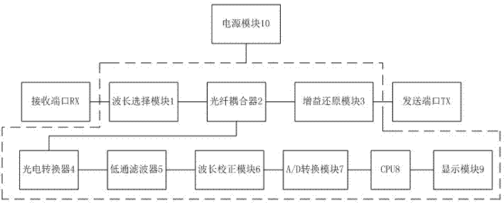
[0011] Such as figure 1 As shown, the optical power real-time monitoring device involved in the present invention includes a receiving port RX, a wavelength selection module 1 connected to the receiving port interface RX, the wavelength selection module is also connected to an optical fiber coupler 2, and the optical fiber The coupler 2 is connected to the gain restoration module 3 and the photoelectric converter 4 respectively, and the gain restoration module 3 is connected to the sending port TX; the photoelectric converter 4 is connected to the low-pass filter 5, and the low-pass filter 5 Also be connected with wavelength correction module 6, described wavelength correction module 6 is also connected with A / D conversion module 7, and described A / D conversion module 7 is also connected with CPU8, and described CPU8 is also connected with d...


PUM


Abstract

The present invention proposes a device for real-time monitoring of optical power, the device includes two receiving ports, the receiving ports are connected to a wavelength selection module, the wavelength selection module is also connected to a fiber The device is connected with the gain restoration module and the photoelectric converter respectively, and the gain restoration module is connected to two sending ports respectively; the photoelectric converter is connected to the low-pass filter, and the low-pass filter is also connected with the wavelength correction module The wavelength correction module is also connected to the A / D conversion module, the A / D conversion module is also connected to the CPU, and the CPU is also connected to the display module; each of the above modules is powered by a power supply module. The optical power real-time monitoring device involved in the present invention can quickly locate the fault area according to the optical power value displayed by the display module, and according to the difference of the fault area, the centralized technical personnel can eliminate the defect, which greatly reduces unnecessary personnel dispatch and shortens the time. Elimination time.

Description

technical field [0001] The invention relates to the field of electric power, in particular to an optical power real-time monitoring device for real-time monitoring of receiving and luminous power of an optical fiber longitudinal difference protection device. Background technique [0002] In the power system, lines with a voltage level of 220kV and above are protected by optical fiber longitudinal differential protection devices, so as to realize the quick action function of the whole line. The optical fiber differential protection device exchanges the optical signals carrying the information on both sides of the line through the optical fiber channel, so as to judge the faults inside and outside the area, so as to realize the quick action function of the whole line. [0003] Whether the optical fiber differential protection device can operate correctly and reliably depends directly on whether the optical fiber longitudinal differential protection device can receive and recei...

Claims


Application Information

Patent Timeline
Patent Type & Authority Patents(China)
IPC IPC(8): G01J1/42G01R31/08
Inventor 李刚辛昂倍岑旭刘震刘天祥王芃高培钧王嫚嫚
Owner STATE GRID CORP OF CHINA
Why Eureka
Eureka Blog
Learn More