Energy-saving geoheat floor ground surface drainage structure

A floor and structure technology, applied in the field of ground drainage structure of energy-saving geothermal buildings, can solve the problems of not considering floor drainage and improper structure, etc.

Inactive Publication Date: 2015-06-10
陈祥环
View PDF0 Cites 0 Cited by
  • Summary
  • Abstract
  • Description
  • Claims
  • Application Information

AI Technical Summary

Problems solved by technology

[0002] At present, the drainage problem of the floor is not considered during the ground construction of the geothermal building. After the geothermal pipe leaks, the water will flow through the floor to the downstairs, causing undue losses due to improper construction.

Method used


Image

  • Energy-saving geoheat floor ground surface drainage structure

Examples


Embodiment Construction

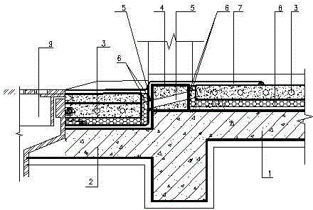
[0007] like figure 1 As shown, an energy-saving geothermal building ground drainage structure, the bedroom floor is 70mm lower than the bathroom floor, 40mm EPS boards are laid on the bedroom and bathroom floors, and a layer of heat insulation is laid on it, and then 50mm thick C20 fine stone concrete A geothermal pipe with a diameter of 25mm is buried in the center, and a 200mm high C20 fine stone concrete guide wall is made at the bottom of the wall between the bedroom and the bathroom, and a DN32 steel casing is embedded in it, and the casing is inclined to the bathroom, and the floor of the bathroom is waterproof The layer is the top surface of the guide wall and extends horizontally for 300 as a waterproof reinforcement layer, and the building sealant is used to seal between the casing and the ground. In this way, water leakage on the floor of the geothermal building due to rupture of geothermal pipes can be discharged to the bathroom through the floor drain.


PUM


Abstract

The present invention discloses an energy-saving geoheat floor ground surface drainage structure, which comprises a bedroom floor (1), a toilet floor (2), a geoheat pipe (3), fine stone concrete (4), a bushing (5), a sealing glue (6), a waterproof material reinforcing layer (7), a thermal insulating layer (8), and a floor drain (9). With the structure of the present invention, the bushing is pre-embedded on the bottom portion of the wall between the bedroom and other life rooms and the toilet, and the waterproof reinforcing layer is paved, such that the leaked water caused by the geoheat pipe breaking and the like on the geoheat floor ground surface can be drained to the toilet so as to be drained through the floor drain, such that the downstairs loss caused by the water leakage can be avoided.

Description

technical field [0001] The invention relates to a ground drainage structure of a building, in particular to a ground drainage structure of an energy-saving geothermal building. Background technique [0002] At present, the floor drainage problem is not considered during the ground construction of the geothermal building. After the geothermal pipe leaks, the water will flow through the floor to the downstairs, causing unnecessary losses due to improper construction. Contents of the invention [0003] The object of the present invention is to overcome the above disadvantages and provide an energy-saving geothermal floor drainage structure. In order to achieve the above object, the technical solution of the present invention is: an energy-saving geothermal building ground drainage structure, which consists of bedroom floor (1), bathroom floor (2), geothermal pipe (3), fine stone concrete (4), sleeve Pipe (5), sealant (6), waterproof material reinforcement layer (7), insulati...

Claims


Application Information

Patent Timeline
Patent Type & Authority Applications(China)
IPC IPC(8): E03C1/12E03F5/04
CPCE04B5/48E03F5/0407
Inventor 陈祥环
Owner 陈祥环
Why Eureka
Try Eureka