
relay device

A relay device and diagnostic request technology, applied in the direction of data exchange, transmission system, registration/instruction, etc. through path configuration, can solve the problems of complex diagnostic association processing and exhaustion of identification information

Inactive Publication Date: 2018-01-02
DENSO CORP
View PDF6 Cites 0 Cited by
  • Summary
  • Abstract
  • Description
  • Claims
  • Application Information

AI Technical Summary

Problems solved by technology

[0008] In this way, in communication protocols of various communication standards, there may be restrictions on the identification information that can be used in diagnostic frames.
However, in the future, it is expected that tools for diagnosis will further diversify, and the number of ECUs mounted on vehicles will increase. As a result, there is a concern that such identification information will be exhausted.
[0009] In addition, each ECU needs to perform different processing according to the type of identification information of the received frame. If the identification information for diagnosis increases due to the diversification of tools for diagnosis, etc., there is a possibility that the diagnosis-related processing of the ECU will become complicated. question

Method used


Image

  • relay device
  • relay device
  • relay device

Examples


Deformed example 1

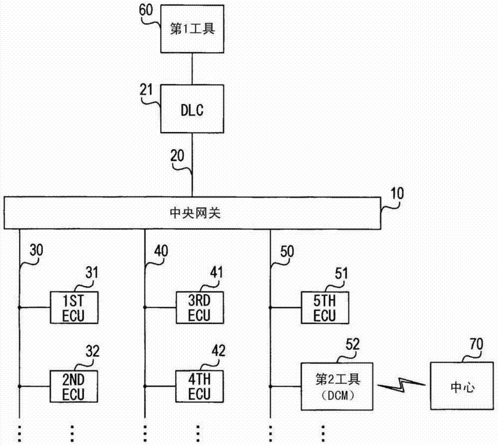
[0113] However, when the fault diagnosis by both the first tool 60 and the second tool 52 is performed simultaneously, it may not be possible to determine which tool the response frame received from the ECU targeted for the fault diagnosis is for. Therefore, it is conceivable to use the central GW 10 to mediate and prevent simultaneous failure diagnosis by both tools. Below, use Figure 5 An example of such mediation will be described.

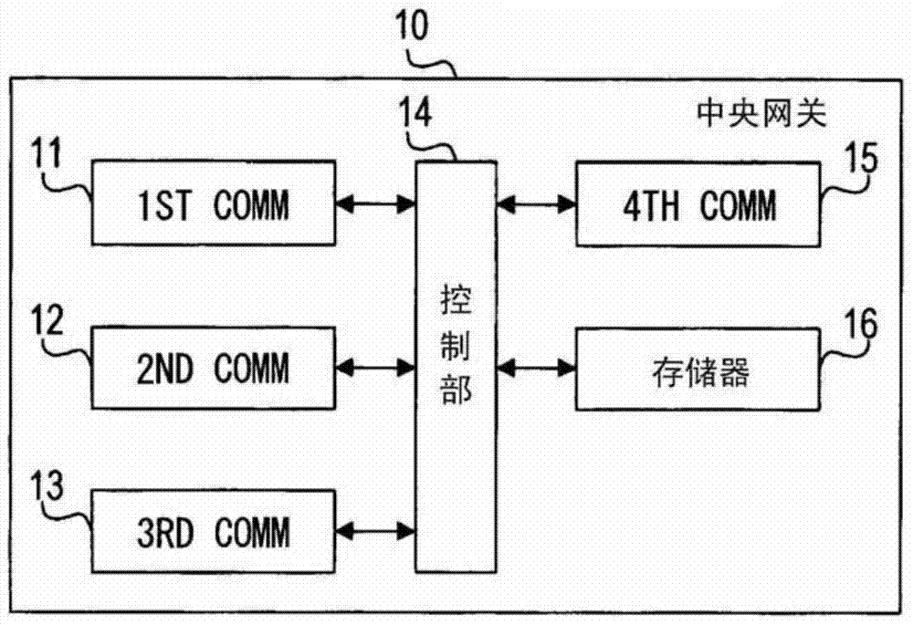
[0114] It is assumed that the second tool 52 transmits the FFD readout to the first ECU 31 to the third LAN 50 (S300). At this time, the control unit 14 of the central GW 10 receives the FFD readout via the third communication unit 13 .

[0115] At this time, the control unit 14 of the central GW 10 starts the mediation process for preventing simultaneous failure diagnosis by each tool (S302), and converts the received ID read by the FFD to the first to The third LANs 30 to 50 send out (S304).

[0116] Then, the first ECU 31 starts diagnos...

Deformed example 2

[0132] As already mentioned, priority is specified in the communication protocol of the application layer of CAN, namely ISO 14229. However, there is also a case where the ECU is configured based on the following rule (last priority): when the ECU receiving the previous diagnosis request frame or the like transmits the next diagnosis request frame or the like from another tool, the ECU When a subsequent diagnostic request frame or the like is received, the processing based on the preceding diagnostic request frame or the like is interrupted, and the processing based on the subsequent diagnostic request frame or the like is started.

[0133] Below, use Figure 6 When the ECU is configured based on the later priority, the process of mediation for prioritizing the fault diagnosis by the first tool 60 will be described.

[0134] It is assumed that the second tool 52 transmits the FFD readout for the first ECU 31 to the third LAN 50 (S400). At this time, the control unit 14 of th...


PUM


Abstract

The relay device (10) includes a request reception unit, a request storage unit, a request conversion unit (S105), a request transmission unit, a response reception unit, a response storage unit, a response conversion unit (S125), and a response transmission unit. When receiving a diagnosis request for diagnosing a failure of the ECU mounted on the vehicle from the first diagnosis tool, the relay device responds to the diagnosis request between the first diagnosis tool and the ECU and to the diagnosis request. Diagnostic responses are relayed. When the relay device receives a target diagnosis request for ECU failure diagnosis from the second diagnosis tool, a diagnosis request between the second diagnosis tool and the ECU, and a diagnosis response as a response to the diagnosis request After the identification information is converted, the diagnostic request and diagnostic response are relayed.

Description

[0001] This invention is based on the Japanese application number 2012-224393 for which it applied on October 9, 2012, and uses the description content here. technical field [0002] The present invention relates to an in-vehicle relay device for relaying communication between a diagnostic tool and an electronic control unit (ECU) to be diagnosed. Background technique [0003] Conventionally, a controller area network (CAN) is known as a communication standard of an in-vehicle local area network (LAN) used in an in-vehicle system, and it is known that a maintenance tool is connected to the CAN via a data link connector at a retailer, etc. Fault diagnosis (diagnosis) of the ECU constituting the in-vehicle system. [0004] In addition, ECUs that wirelessly communicate with the outside are known. As an example of such an ECU, a remote control device that wirelessly communicates with a portable device and accepts remote operations via the portable device is known (Patent Documen...

Claims


Application Information

Patent Timeline
Patent Type & Authority Patents(China)
IPC IPC(8): H04L12/44H04L12/46
CPCH04L2012/40273H04L12/4625H04L2012/40293H04L12/44H04L12/46G05B23/0205G05B23/0216G07C5/006G07C5/008G07C5/0808G07C5/0816G07C5/0858G07C2205/02H04L69/28
Inventor 原田雄三夏目充启高桥康行
Owner DENSO CORP
Learn More