
Shallow geothermal energy device with pumping and recharging in same well

A geothermal energy and shallow layer technology, which is applied in the field of shallow geothermal energy co-well recharge device, achieves the effects of facilitating popularization and implementation, good use effect and improved efficiency

Inactive Publication Date: 2016-02-24
HENAN RUNHENG ENERGY MANAGEMENT
View PDF10 Cites 8 Cited by
  • Summary
  • Abstract
  • Description
  • Claims
  • Application Information

AI Technical Summary

Problems solved by technology

The shortcomings of the "multi-well recharge" method have become a bottleneck in the promotion and development of water source heat pump central air conditioning

Method used


Image

  • Shallow geothermal energy device with pumping and recharging in same well
  • Shallow geothermal energy device with pumping and recharging in same well
  • Shallow geothermal energy device with pumping and recharging in same well

Examples


Embodiment 1

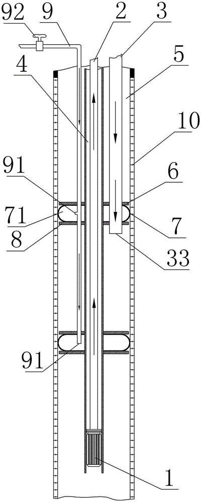
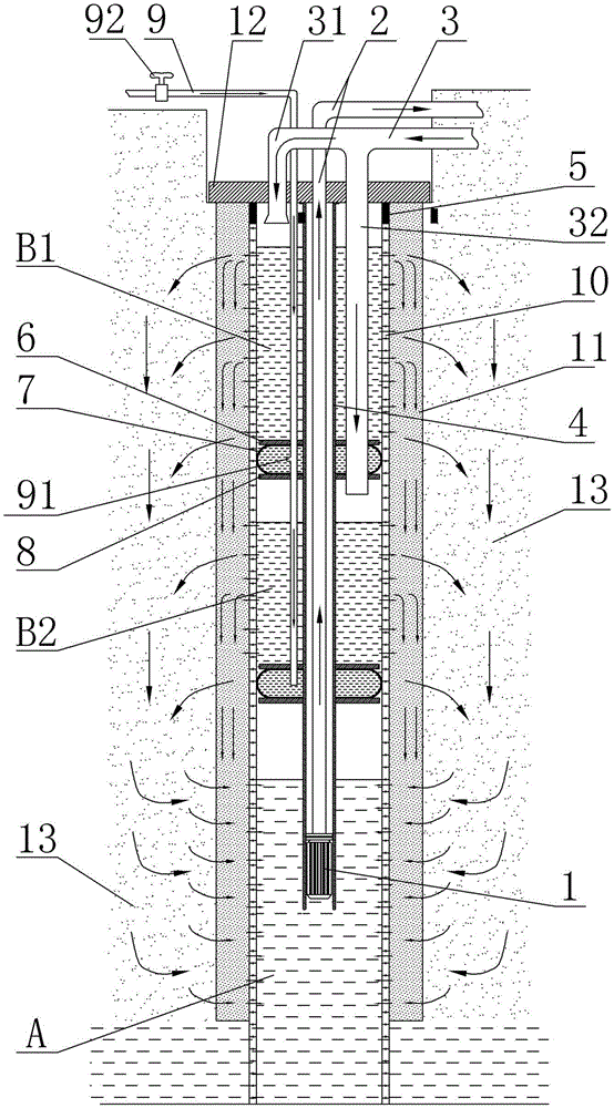
[0029] Example 1: A shallow geothermal energy recharge device in the same well, see figure 1 , including a support permeable pipe 5 set on the inner side of the water source well and an inner water pipe 4 arranged in the support permeable pipe, the cavity of the support permeable pipe 5 and the inner water pipe 4 is provided with a return pipe 6 (or return branch pipe) The high-pressure pipe 9 and the inner water pipe 4 are provided with an outlet pipe 2, the water inlet of the outlet pipe is connected to the submersible pump 1, and an insulating interlayer is arranged between the inner water pipe 2 and the outlet pipe 4. The water return pipe 3 is used for connecting with the high-pressure water return device, and the high-pressure pipe 9 is used for connecting with the high-pressure water supply device.

[0030] In order to achieve a better return water effect, multiple sealed return water spaces can be set up to perform return water and heat exchange through multiple chann...

Embodiment 2

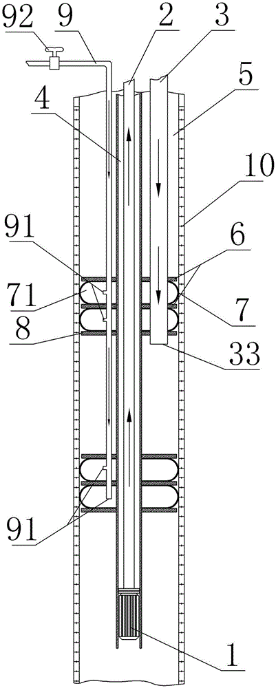
[0035] Example 2: see image 3 , The content is basically the same as in Example 1, the difference is that each group of sealing rings is composed of two sealing rings, a lower pressing plate and two upper pressing plates, and the sealing rings are arranged at intervals with the upper and lower pressing plates.

Embodiment 3

[0036] Embodiment 3: The drawings are not drawn, and the content is basically the same as that of Embodiment 1, except that the number of return water pipes is one, and the return water pipes are provided with water outlets in each return water space.


PUM


Abstract

A shallow geothermal energy device with pumping and recharging in the same well comprises a water permeable pipe and an inner water pipe. A water outlet pipe is arranged in the inner water pipe. A water inlet of the water outlet pipe is connected with a submersible pump. A water returning pipe is arranged in an annular cavity supporting the water permeable pipe and the inner water pipe. A high-pressure pipe is arranged in the annular cavity supporting the water permeable pipe and the inner water pipe. The surface of the outer circle of the inner water pipe is fixedly provided with n sealing ring sets. Each sealing ring set comprises a sealing ring, an upper pressing plate and a lower pressing plate, and the upper pressing plate and the lower pressing plate are arranged on the upper side face and the lower side face of the sealing ring. Each sealing ring is a hollow elastic annular ring. The upper pressing plates and the lower pressing plates are all fixedly arranged on the periphery of the inner water pipe in a sleeving manner. The portion, stretching into the sealing rings, of the high-pressure pipe is provided with a high-pressure pipe outlet. According to the shallow geothermal energy device with pumping and recharging in the same well, the sealing rings on the inner water pipe and the inner pipe wall supporting the water permeable pipe form a plurality of isolation layers and independent and closed water returning spaces, and therefore the water returning pipe can be pressed into the different water returning spaces, and the purpose of a plurality of water returning paths is achieved.

Description

technical field [0001] The invention relates to the problem of water source well recharge in the technical field of geothermal energy heat pump central air conditioning, in particular to a shallow geothermal energy common well recharge device. Background technique [0002] Geothermal energy heat pump central air conditioning (also known as "water source heat pump central air conditioning") uses groundwater with a constant temperature for many years as the transmission medium of geothermal energy. Through the heat pump unit, the water temperature is raised or lowered to achieve cooling and heating purposes. Central air-conditioning that provides cold and heat sources. Because of its high energy efficiency ratio, it saves 40-60% energy compared with other traditional forms of central air conditioners, and has a remarkable effect of energy saving and consumption reduction. It is gradually favored by governments, agencies, and business units, and has also been recognized by most...

Claims


Application Information

Patent Timeline
Patent Type & Authority Applications(China)
IPC IPC(8): F24J3/08
CPCY02E10/10
Inventor 牛青锋索凤李玉军刘进管其烛
Owner HENAN RUNHENG ENERGY MANAGEMENT
Learn More