Probe point measurement system

A probe and point measurement technology, which is applied in the field of probe point measurement system, can solve problems such as difficulty in finding abnormalities of incoming wafers, poor contact of contacts, and contact with wafers, etc.

Active Publication Date: 2015-06-17
MICROELECTRONICS TECH INC
View PDF10 Cites 7 Cited by
  • Summary
  • Abstract
  • Description
  • Claims
  • Application Information

AI Technical Summary

Problems solved by technology

If the probe does not have enough needle pressure, there will be poor contact with the wafer, making the measurement data of the wafer inaccurate
In addition, if the needle pressure of the probe is too large, it is easy to damage the probe or cause damage to the wafer surface
[0003] When the traditional edge finder touches the wafer with its probe, it takes a period of time (for example, 20ms) to confirm whether the probe is in contact with the wafer, so it is not easy to shorten the detection time
In addition, when some of the probes on the existing edge fi

Method used


Image

  • Probe point measurement system
  • Probe point measurement system
  • Probe point measurement system

Examples


Embodiment Construction

[0024] A number of implementations of the present invention will be disclosed below with the accompanying drawings, and many specific details will be described together in the following description for the sake of clarity. It should be understood, however, that these specific details should not be used to limit the invention. That is, in some embodiments of the invention, these specific details are not necessary. In addition, for the sake of simplification of the drawings, some conventional structures and elements will be shown in a simple and schematic manner in the drawings.

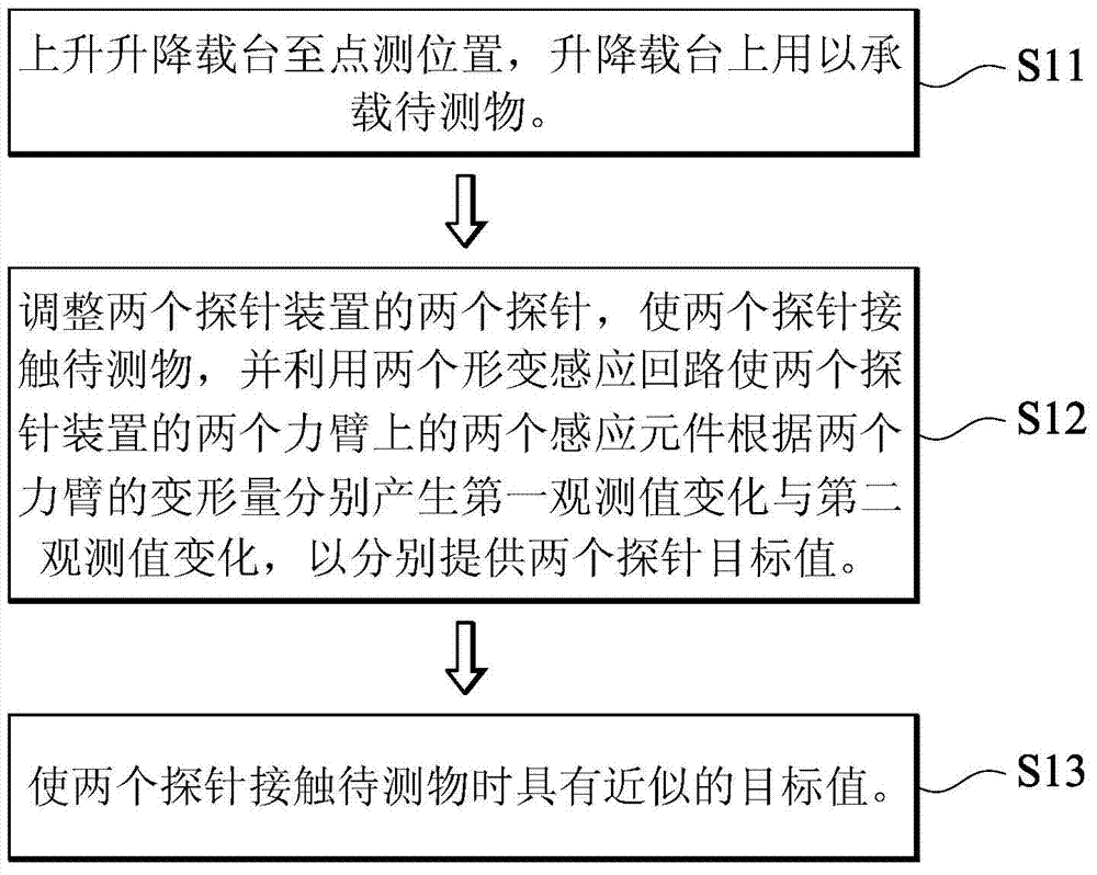
[0025] figure 1 It is a flowchart of a probe height adjustment method according to an embodiment of the present invention. Firstly, in step S11 , the lift platform is raised to the spot measurement position, and the lift platform is used to carry the object to be tested. Then in step S12, adjust the two probes of the two probe devices so that the two probes contact the object to be tested, and use t...


PUM


Abstract

The invention discloses a probe point measurement system, comprising a lifting table, at least one probe apparatus, at least one deformation sensing loop, a contact sensing loop, a test loop, a first switch and a second switch. The lifting table is used for carrying a to-be-tested object. The probe apparatus is positioned above the lifting table. The probe apparatus comprising a moment arm, a probe and at least one sensing element. One end of the moment arm is connected to the probe. The sensing element is on the moment arm. When the moment arm is deformed by bearing a force, the sensing element generates observed value change along the deformation of the moment arm. The deformation sensing loop is electrically connected with the sensing element and used for receiving the observed value change. The contact sensing loop comprises a power supply and a probe pressure sensing unit. The probe pressure sensing unit is electrically connected with the power supply, and has a pressure increasing element and a probe connection line. The probe spot measurement system shortens the time for detecting the to-be-tested object through the contact sensing loop, and ensures that the probe abuts against the to-be-tested object at a preset probe pressure through the deformation sensing loop.

Description

technical field [0001] The invention relates to a probe point measuring system. Background technique [0002] The traditional edge sensor (edge ​​sensor) must manually adjust the tightness of the elastic element (such as a spring), and then adjust the needle pressure of the probe. When the stage carrying the wafer rises up to touch the probe of the edge finder, the probe will be supported by the wafer and move upward. If the probe does not have enough needle pressure, the contact with the wafer will be poorly contacted, and the measurement data of the wafer will be inaccurate. In addition, if the needle pressure of the probe is too large, it is easy to damage the probe or cause damage to the wafer surface. [0003] It takes a period of time (for example, 20 ms) to confirm whether the probes are actually in contact with the wafer when the probes of the traditional edge finder touch the wafer, so it is difficult to shorten the detection time. In addition, when some of the p...

Claims


Application Information

Patent Timeline
IPC IPC(8): G01R1/02G01R31/26
Inventor 彭柏翰黄大猷
Owner MICROELECTRONICS TECH INC
Why Eureka
Try Eureka