A kind of sine wave permanent magnet synchronous motor with low cogging effect and its manufacturing method

A cogging effect and synchronous motor technology, which is applied to synchronous motors with stationary armatures and rotating magnets, synchronous machine parts, manufacturing motor generators, etc., can solve the problem of poor cogging effect inhibition and the influence of sine wave permanent Magnetic synchronous motor output efficiency and other issues to achieve the effect of improving stability, improving stability and control accuracy, and improving the back EMF waveform

Active Publication Date: 2017-08-22
LIYANG HONGDA MOTORS
View PDF7 Cites 0 Cited by
  • Summary
  • Abstract
  • Description
  • Claims
  • Application Information

AI Technical Summary

Problems solved by technology

[0003] The technical problem to be solved by the present invention is that the existing sine wave permanent magnet synchronous motor has poor cogging suppression effect, which affects the output efficiency of the sine wave permanent magnet synchronous motor

Method used


Image

  • A kind of sine wave permanent magnet synchronous motor with low cogging effect and its manufacturing method
  • A kind of sine wave permanent magnet synchronous motor with low cogging effect and its manufacturing method
  • A kind of sine wave permanent magnet synchronous motor with low cogging effect and its manufacturing method

Examples


Embodiment Construction

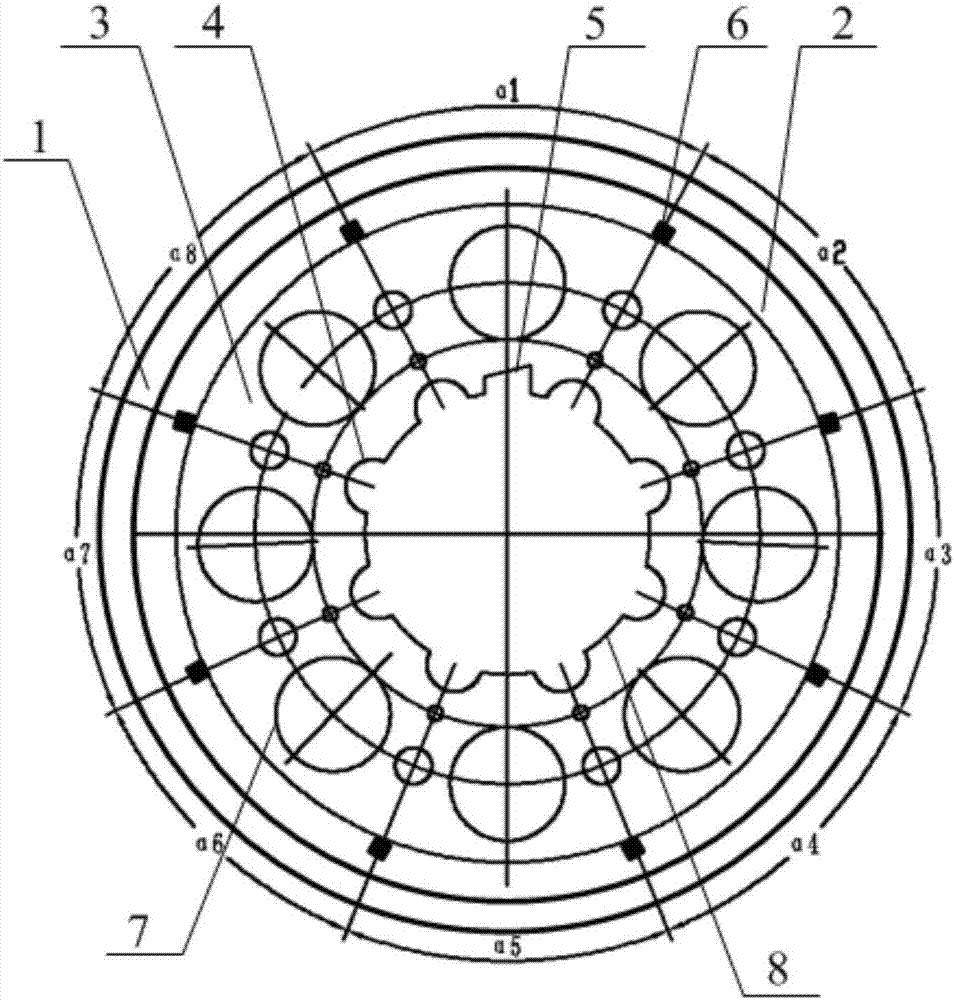
[0022] Such as figure 1 As shown, the sine wave permanent magnet synchronous motor with low cogging effect of the present invention includes: a semi-closed slot punched stator and a surface-mounted rare earth permanent magnet material excitation rotor. The sine wave permanent magnet synchronous motor is a three-phase motor and has a phase band. It is 60°, and there are 36 stator slots in the semi-closed slot punched stator.

[0023] The surface-mounted rare earth magnetic material excitation rotor includes a steel sleeve 1, eight magnets 2 and rotor punching pieces 3. Among them, a rotor shaft mounting hole 8 is provided at the center of the rotor blade 3, and eight semicircular synchronization notches 4 are provided on the circumferential edge of the rotor shaft mounting hole 8; and the outer circumference of the rotor blade 3 is provided There are eight positioning teeth 6, and eight pieces of magnetic steel 2 are glued and fixedly installed between two positioning teeth 6; the...


PUM


Abstract

The invention provides a sine wave permanent magnet synchronous motor with low cogging effect and its manufacturing method, wherein the motor includes a semi-closed slot punched stator and a surface-mounted rare earth permanent magnet material excitation rotor, and the semi-closed slot is punched There are 36 stator slots in the stator; the surface-mounted rare earth magnetic material excitation rotor includes steel sleeves, magnetic steel and rotor punching pieces; eight magnetic steels are installed between two positioning teeth, and the steel sleeves are set on eight magnets steel perimeter. The manufacturing method includes the following steps: calculating the number of slots corresponding to each pole and each phase, distributing the magnetic pole angle range occupied by the magnetic poles on the circumference of the rotor, setting positioning teeth with corresponding arc spacing, fixing the magnetic steel between the positioning teeth, A steel sleeve is placed on the outer periphery of the steel, and the rotor is rotatably installed in the stator. The motor and its manufacturing method reasonably distribute the magnetic poles on the rotor circumference, so that the cogging reluctance of the rotor at any angle within the 360° mechanical angle of the stator circumference is equal, and the stability and control accuracy of the motor torque are improved.

Description

Technical field [0001] The invention provides a sine wave permanent magnet synchronous motor and a manufacturing method thereof, in particular a sine wave permanent magnet synchronous motor with low cogging effect and a manufacturing method thereof. Background technique [0002] The cogging effect of rare earth permanent magnet synchronous motors is an undesirable effect that has always existed since the advent of permanent magnet synchronous motors, and it is a thorny problem that electrical engineers have to find a way to solve. Looking at permanent magnet motors at home and abroad, engineers have thought of many methods, such as: stator punching using closed slots; open slot magnetic slot wedges; stator skewed slots; rotor slanted poles; Siemens motors use spaced magnetic short circuit design ideas and other methods. Judging from the suppression results, the Siemens motor has the best effect. No other methods can effectively weaken the adverse effects of cogging. However, th...

Claims


Application Information

Patent Timeline
Patent Type & Authority Patents(China)
IPC IPC(8): H02K21/14H02K1/27H02K21/02H02K15/00
Inventor 靳昱童小春高春香
Owner LIYANG HONGDA MOTORS
Why Eureka
Try Eureka