Built-in type permanent magnet synchronous motor

A permanent magnet synchronous motor, built-in technology, applied to synchronous machines, synchronous motors with stationary armatures and rotating magnets, synchronous machine parts, etc., can solve the difficulty of designing multi-segment lines on the outer contour of the rotor and weaken the motor Noise and vibration, unsatisfactory application effects and other problems, to achieve the effect of improving the back EMF waveform, optimizing performance, and easy implementation

Inactive Publication Date: 2015-06-24
KINGCLEAN ELECTRIC
View PDF5 Cites 9 Cited by
  • Summary
  • Abstract
  • Description
  • Claims
  • Application Information

AI Technical Summary

Problems solved by technology

[0006] The part of the stator tooth of the traditional built-in permanent magnet synchronous motor facing the air gap is a concentric arc edge. By making the outer contour of the rotor into a polyline, the distance between the stator tooth and the outer ring of the rotor is not equal (such as image 3 As shown), so as to form an uneven air gap to optimize the back EMF waveform, but it is difficult to design the outer contour of the rotor with a polyline, and the application effect is not ideal in the pole-slot coordination where the number of slots per pole and phase is q=1 / 2 , it is difficult to optimize motor performance and reduce motor noise and vibration

Method used


Image

  • Built-in type permanent magnet synchronous motor
  • Built-in type permanent magnet synchronous motor
  • Built-in type permanent magnet synchronous motor

Examples


Embodiment

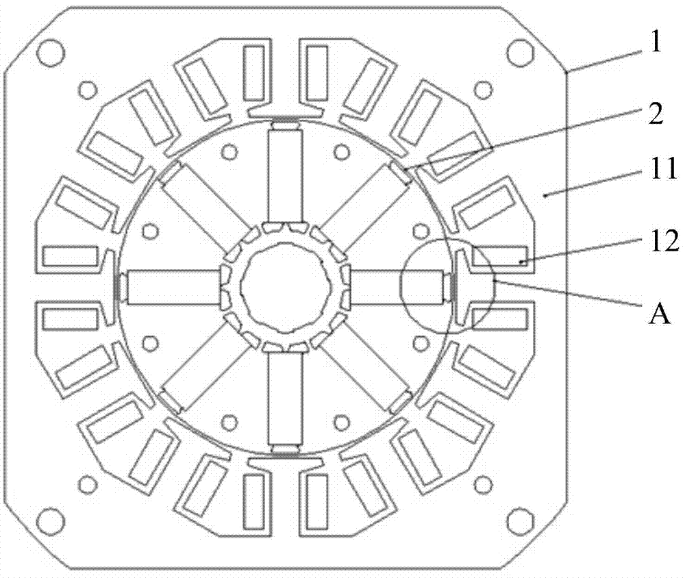
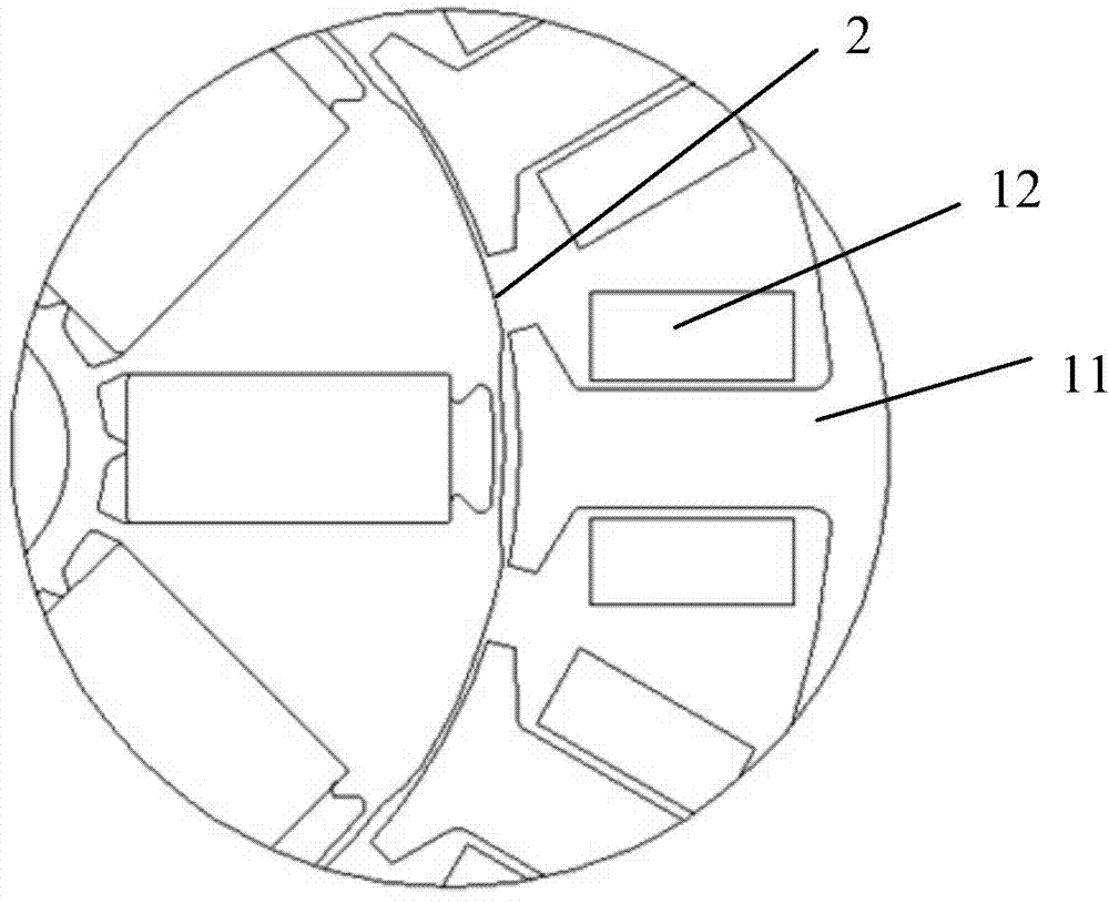
[0041] Please also see figure 1 and figure 2 , as shown in the figure, a built-in permanent magnet synchronous motor includes a stator 1 and a rotor 2. There is an air gap between the inner ring of the stator 1 and the outer ring of the rotor 2. The stator 1 includes a stator core 11 and a winding 12. The stator iron The side of the teeth of the core 11 opposite to the air gap has a linear structure, and the outer ring of the rotor 2 has a perfect circular structure, and there is an air gap space between the teeth and the outer ring of the rotor. In this way, an uneven air gap is formed, which can effectively optimize the performance of the motor, significantly improve the back EMF waveform of the motor, effectively weaken the cogging torque, and suppress the noise and vibration of the motor.

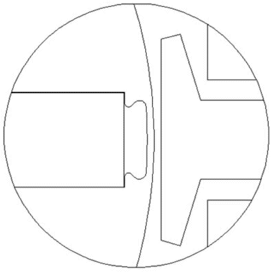
[0042] Correspondingly, such as image 3 As shown, the part of the stator teeth facing the air gap is a concentric arc edge, and the outer contour of the rotor is a polyline, forming...


PUM


Abstract

The invention discloses a built-in type permanent magnet synchronous motor. The built-in type permanent magnet synchronous motor comprises a stator and a rotor, and an air gap is reserved between the inner ring of the stator and the outer ring of the rotor; the stator comprises a stator iron core and windings, and one side, opposites to the air gap, of each tooth portion of the stator iron core is of a straight line structure or a non-concentric arc-shaped structure; the outer ring of the rotor is of a circular structure, and the non-isometric air gap space is formed between the tooth portions of the stator and the outer ring of the rotor. No multistage design is required for the outer ring of the rotor according to the structure of the motor, the outer ring of the rotor can be of a traditional circular structure, and the air gap between the inner ring of the stator of the motor and the outer ring of the rotor is non-isometric, so that the uneven air gap is formed; the performance of the motor can be effectively optimized, the counter electromotive force waveform of the motor can be obviously improved, the torque of tooth grooves can be effectively weakened, and the noise and vibration of the motor are restrained; the design is simple, the operation is convenient, and the implementation is easy.

Description

technical field [0001] The invention belongs to the technical field of motor structure design, and in particular relates to a built-in permanent magnet synchronous motor. Background technique [0002] Motor refers to an electromagnetic device that realizes the conversion or transmission of electric energy according to the law of electromagnetic induction. Its main function is to generate driving torque as a power source for electrical appliances or various machinery. [0003] Motors can be divided into DC motors, asynchronous motors, and synchronous motors according to their structure and working principle. Synchronous motors usually include permanent magnet synchronous motors, reluctance synchronous motors, and hysteresis synchronous motors. [0004] At present, the energy efficiency index of motors is increasingly valued by the government and the market, and it is also true in the field of white goods. The series excitation motor, frequency conversion induction motor, and...

Claims


Application Information

Patent Timeline
Patent Type & Authority Applications(China)
IPC IPC(8): H02K21/16H02K21/02
CPCH02K21/16H02K21/026
Inventor 倪祖根
Owner KINGCLEAN ELECTRIC
Why Eureka
Try Eureka