
Permanent magnet switch magnetic flux linkage motor

A technology of permanent magnet switch and flux linkage, which is applied to the static parts of the magnetic circuit, the shape/style/structure of the magnetic circuit, etc., can solve the problems of increased production scrap rate, deformation of the inner circle of the stator, deformation of the punching plate, etc., and achieves optimal feedback. Potential waveform, effect of reducing harmonic content, increasing mechanical strength

Active Publication Date: 2014-03-26
ZHUHAI GREE REFRIGERATION TECH CENT OF ENERGY SAVING & ENVIRONMENTAL PROTECTION
View PDF4 Cites 4 Cited by
  • Summary
  • Abstract
  • Description
  • Claims
  • Application Information

AI Technical Summary

Problems solved by technology

Since the connection part of the punching sheet is very thin, it is easy to cause deformation and breakage of the punching sheet, which increases the production scrap rate
In addition, the laminated iron core also has the disadvantage of poor mechanical strength, and the inner circle of the stator is easily deformed due to external pressure, which in turn affects the operating performance of the motor.

Method used


Image

  • Permanent magnet switch magnetic flux linkage motor
  • Permanent magnet switch magnetic flux linkage motor
  • Permanent magnet switch magnetic flux linkage motor

Examples


Embodiment Construction

[0030] The invention provides a novel permanent magnet switch flux linkage motor with simple structure. More particularly, the present invention mainly adopts the magnetic isolation hole to replace the conventional magnetic isolation bridge, so that the mechanical strength of the stator core is increased and the processing is convenient. Preferred specific embodiments of the present invention will be described in detail below.

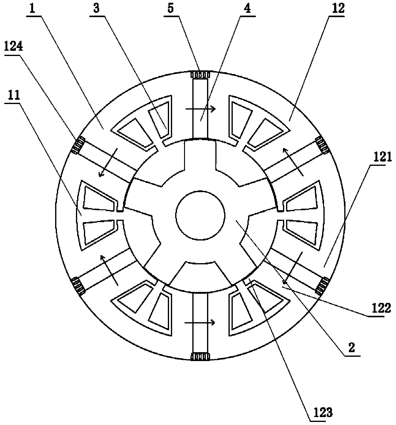
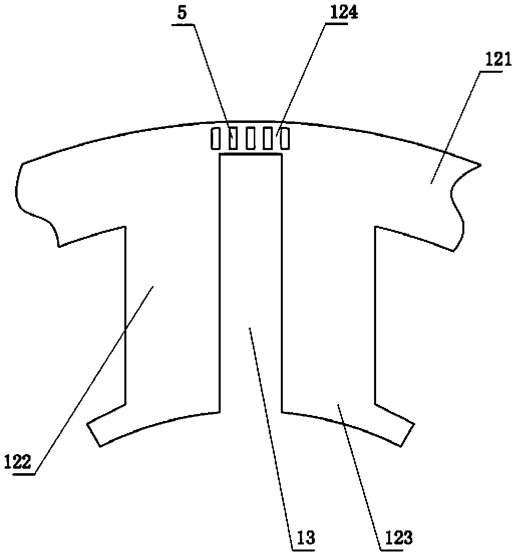
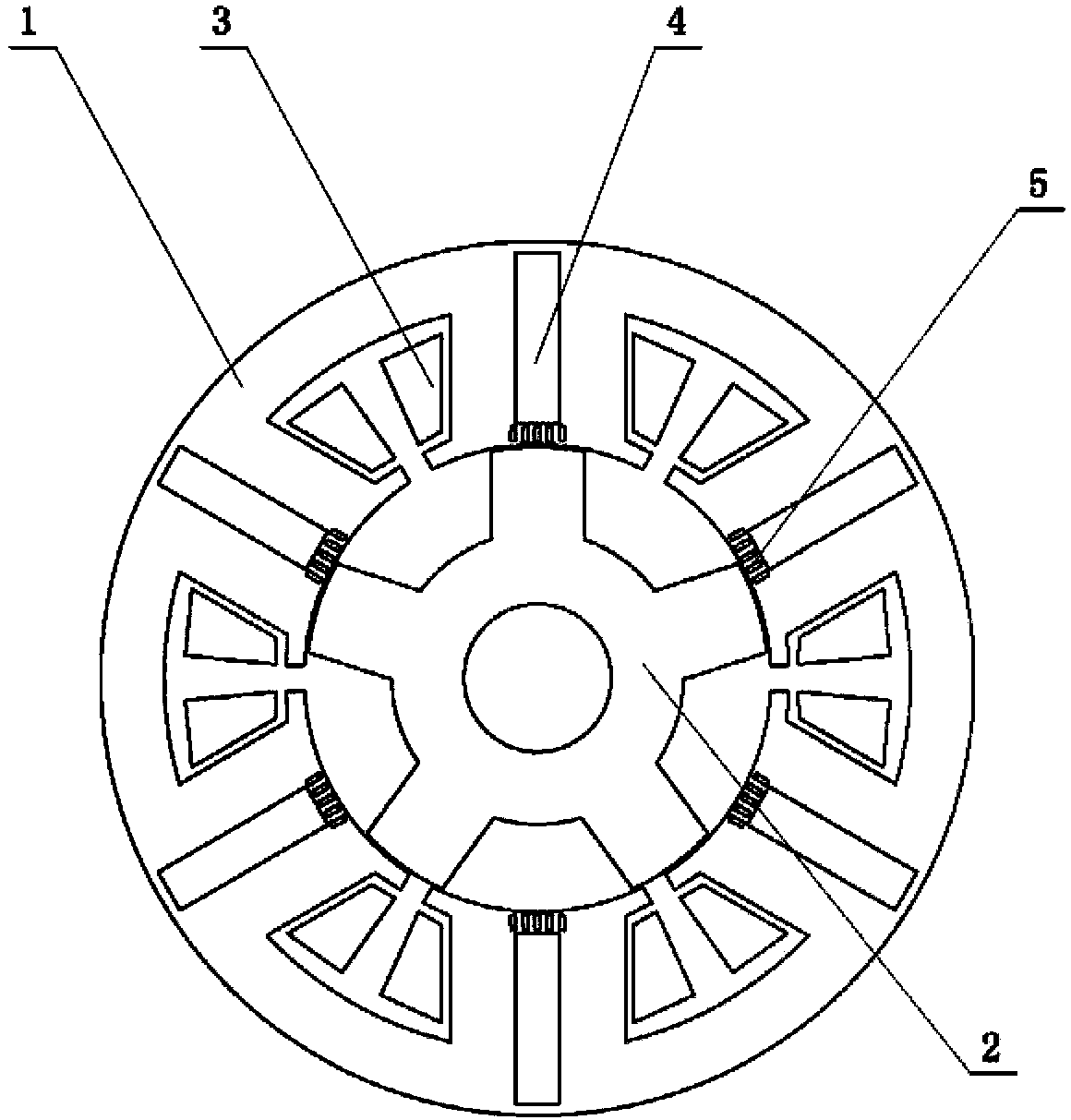
[0031] see Figure 1 to Figure 7 , the present invention provides a permanent magnet switch flux linkage motor, which includes a stator core 1, a rotor core 2, an armature winding 3 and a permanent magnet 4, and the stator core 1 includes several The stator slots 11 evenly distributed in the circumferential direction and the stator teeth 12 between two adjacent stator slots 11 are provided with permanent magnet slots 13 for placing permanent magnets 4 on the stator teeth 12, and the armature winding 3 is arranged on the In the stator slot 11 , a magn...


PUM


Abstract

The invention provides a permanent magnet switch magnetic flux linkage motor comprising a stator iron core, a rotor iron core, armature windings and permanent magnets. The stator iron core comprises multiple stator grooves and stator teeth which are arranged between the adjacent two stator grooves. The stator teeth are provided with permanent magnet grooves used for placing the permanent magnets. The armature windings are arranged in the stator grooves. Magnetic separation holes are arranged on connecting parts of the permanent magnet grooves and the stator teeth. Magnetic separation bridges are substituted by the magnetic separation holes so that area of the connecting parts on the periphery of stator punching sheets is increased, and deformation in the process of assembling, testing and using stators can be reduced. Besides, the magnetic separation holes are additionally arranged in the internal diameters of the stator punching sheets to act as the connecting parts so that mechanical strength of the stators is further enhanced.

Description

technical field [0001] The invention relates to a flux linkage motor, in particular to a permanent magnet switch flux linkage motor. Background technique [0002] Motors are the main drive components in modern industrial systems, and motors with excellent performance are crucial to the entire drive system. In recent years, with the development of power electronics technology, permanent magnet materials and microcomputer control technology, the permanent magnet brushless DC motor has developed rapidly. The permanent magnet brushless DC motor has the characteristics of high efficiency and high power density. With the high performance permanent magnet The advent of materials has greatly improved the power density and performance of permanent magnet brushless DC motors. Switched reluctance motors are used more and more widely because of their simple structure and good reliability. The permanent magnet switched flux linkage motor obtained by placing permanent magnets in the mid...

Claims


Application Information

Patent Timeline
Patent Type & Authority Applications(China)
IPC IPC(8): H02K1/17H02K1/14
Inventor 孙文娇陈彬陈东锁曾学英
Owner ZHUHAI GREE REFRIGERATION TECH CENT OF ENERGY SAVING & ENVIRONMENTAL PROTECTION
Learn More