
Hydraulic systems especially for actuating drive trains

A technology of hydraulic system and transmission system, applied in the field of hydraulic system, can solve the problems of driving off module actuation and cooling loss too much energy, etc.

Active Publication Date: 2017-12-26
NANJING BANGQI AUTOMATIC TRANSMISSION CO LTD
View PDF12 Cites 0 Cited by
  • Summary
  • Abstract
  • Description
  • Claims
  • Application Information

AI Technical Summary

Problems solved by technology

When applying the known hydraulic system to the drive mechanism in a vehicle equipped with a drive away module and a transmission, when the vehicle drives away and / or shifts and if the transmission is set to CVT (continuously variable drive) transmission while it is also operating, too much energy is lost in the actuation and cooling of the drive-away modules

Method used


Image

  • Hydraulic systems especially for actuating drive trains
  • Hydraulic systems especially for actuating drive trains
  • Hydraulic systems especially for actuating drive trains

Examples


Embodiment Construction

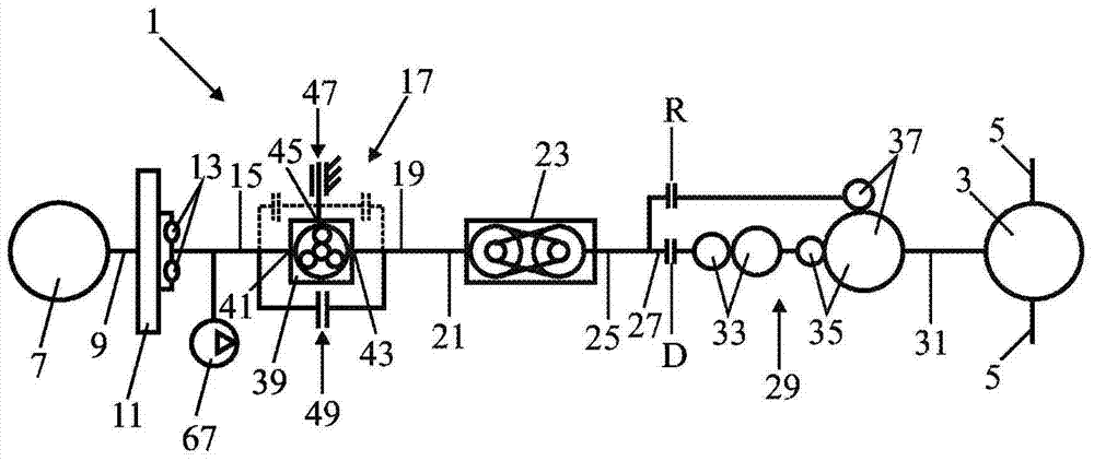
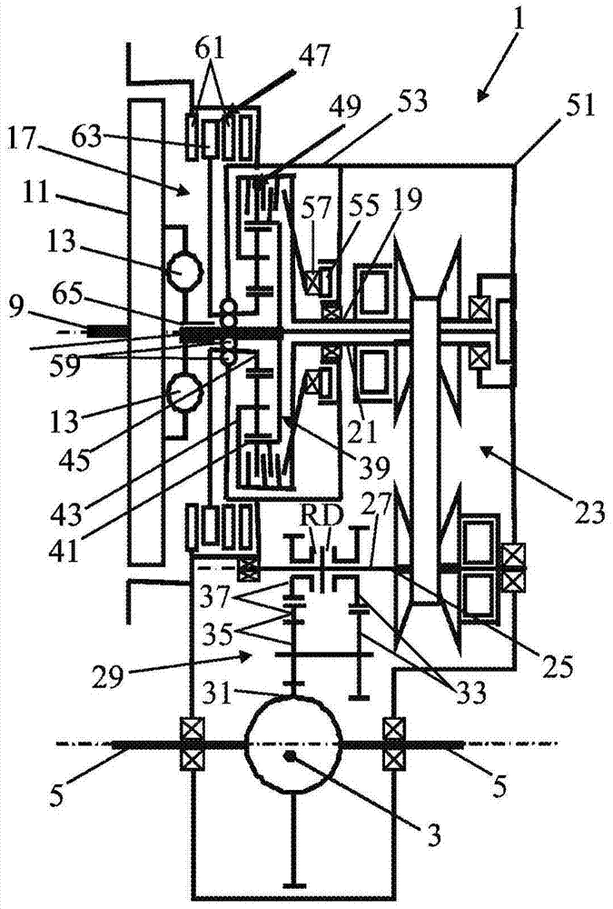
[0051] figure 1 The layout of a drive mechanism equipped with a hydraulic system according to the invention is shown. The drive mechanism 1 is provided in a vehicle, of which only a differential 3 and a drive shaft 5 connected to the wheels are shown. The driving mechanism includes a driving source 7, which is constituted by an internal combustion engine in this embodiment, but may also be constituted by, for example, an electric motor. A flywheel 11 is located on the output shaft 9 of the drive source, the flywheel is connected to the input part 15 of the drive-off module 17 via a torque damper 13 . The output 19 of the drive-off module is connected to an input shaft 21 of a transmission forming part of the drive mechanism. In this embodiment, the transmission is constituted by a CVT transmission 23 in which the output shaft 25 is connected to the input 27 of a final drive 29 forming part of the drive train. The output 31 of the final drive is connected to the differential...


PUM


Abstract

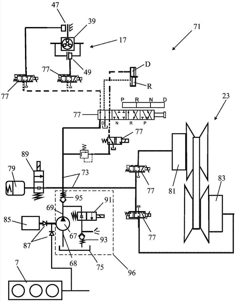
A hydraulic system (71), in particular for actuating a transmission, comprising: an oil pump (67), driven by one of the shafts or drive sources in said transmission, said pump having an input and an output, said The input is connected to the oil tank (75) and the output is connected to the main line (73); a switchable valve (91) is located between the output (69) of the oil pump (67) and the oil tank (75) between; a restriction (93), located between the switchable valve (91) and the oil tank (75); and another valve (95), located at the output (69) of the oil pump (67) and the main line (73). The switchable valve (91) is operated such that the line pressure generated by the oil pump can be lower or higher than the pressure in the main line (73).

Description

technical field [0001] The invention relates to a hydraulic system, in particular for actuating a transmission system, comprising: [0002] an oil pump driven by one of the shafts or drive sources in the transmission, the pump having an input connected to the oil tank and an output connected to the main line, [0003] A switchable valve, located between the output of the oil pump and the oil tank, [0004] a restriction between the switchable valve and the tank, and [0005] Another valve is located between the output of the oil pump and the main line. Background technique [0006] Hydraulic systems of this type for drive mechanisms are generally known. When applying the known hydraulic system to the drive mechanism in a vehicle equipped with a drive away module and a transmission, when the vehicle drives away and / or shifts and if the transmission is set to CVT (continuously variable drive) transmission while it is also operating, too much energy is lost in the actuation...

Claims


Application Information

Patent Timeline
Patent Type & Authority Patents(China)
IPC IPC(8): F16H61/00
CPCB60Y2400/72F16H61/0021F16H61/0206F16H2061/0034F16H61/0031Y10T137/86019F16H61/0025F16H63/065F16H63/3483
Inventor 勒尔·马里·范德鲁滕亚历山大·弗朗西斯库斯·阿尼塔·塞拉恩斯巴斯·赫拉德·弗勒门
Owner NANJING BANGQI AUTOMATIC TRANSMISSION CO LTD
Learn More