Main shaft structure on a vertical shaft impact crusher

A vertical shaft impact and crusher technology, applied in the direction of shafts and bearings, rigid supports of bearing components, bearing components, etc., can solve problems such as inconvenient oil supply, potential safety hazards in equipment operation, and vibration of the main shaft box, and achieve lubricating oil supply And the effect of convenient backflow, reasonable internal oil circuit setting, and increased bearing capacity

Active Publication Date: 2017-03-01
ZHEJIANG ZHEKUANG HEAVY IND CO LTD
View PDF6 Cites 0 Cited by
  • Summary
  • Abstract
  • Description
  • Claims
  • Application Information

AI Technical Summary

Problems solved by technology

In the above-mentioned sand making machine structure, the main shaft group is positioned and installed inside the main shaft seat on the frame. The main shaft group includes the main shaft box and the main shaft, and the main shaft is positioned inside the main shaft box through the bearing; however, its disadvantages are: 1. The main shaft The positioning effect of the box is not good, and it is prone to vibration and offset of the main shaft box, which affects the normal operation of the equipment; 2. The lack of stability of the main shaft generally exists in the main shaft group, which leads to potential safety hazards in the operation of the equipment; 3. The bearing seal of the main shaft group The effect is not good, and it is prone to oil leakage, dust inclusion, etc.; 4. The internal oil passage on the headstock is unreasonably set, resulting in inconvenient oil supply and affecting installation efficiency

Method used


Image

  • Main shaft structure on a vertical shaft impact crusher
  • Main shaft structure on a vertical shaft impact crusher
  • Main shaft structure on a vertical shaft impact crusher

Examples


Embodiment Construction

[0021] The preferred embodiments of the present invention will be described in further detail below in conjunction with the accompanying drawings.

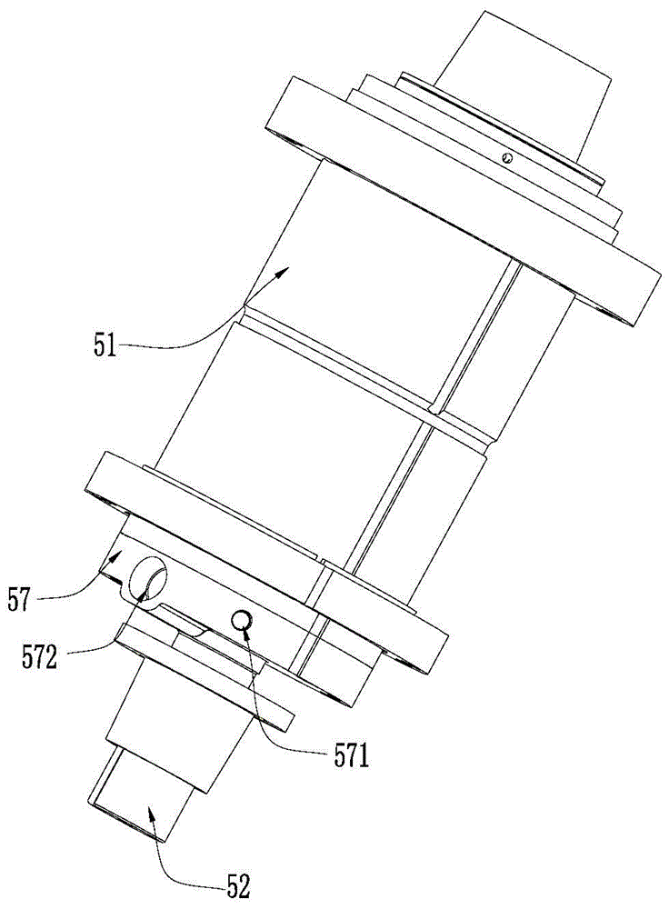
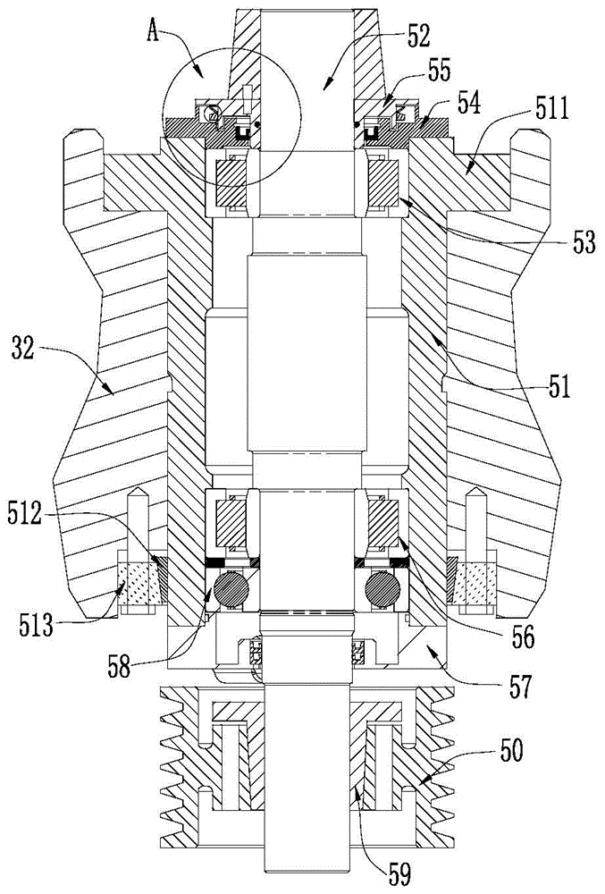
[0022] like Figure 1~Figure 7 The main shaft structure on a vertical shaft impact crusher shown includes a main shaft seat 32 arranged on the frame, and a main shaft group arranged on the main shaft seat; Main shaft 52 inside 51.

[0023] An outwardly protruding flange ring 511 is provided on the upper end of the outer surface of the spindle box 51 , and an inner tapered ring 512 is sleeved on the lower end of the outer surface of the spindle box 51 . The flange ring 511 on the spindle box 51 is erected on the upper end of the spindle base 32 and can be positioned and fixed by bolts. The inner tapered ring 512 at the lower end of the spindle box 51 is inside the main shaft seat 32, and the outer tapered ring 513 is arranged between the inner tapered ring 512 and the main shaft seat 32, and the tapered ring 513 is arranged betwe...


PUM


Abstract

The invention relates to the field of mining equipment, and particularly relates to a main shaft structure on a vertical shaft impact type crusher. The main shaft structure comprises a main shaft base arranged on a rack and a main shaft assembly arranged on the main shaft base, wherein the main shaft assembly comprises a main shaft case and a main shaft which is positioned and arranged in the main shaft case. The main shaft structure has the advantages of stable positioning, good bearing seal effect, reasonable oil path arrangement and the like.

Description

technical field [0001] The invention relates to the field of mining equipment, in particular to a main shaft structure on a vertical shaft impact crusher. Background technique [0002] In the field of mining equipment, the vertical shaft impact crusher is also known as the sand making machine. Its working principle is to divide the material into the throwing material in the middle and the blanking material in the surrounding area. It is thrown at high speed and collides with the surrounding falling materials, and the stones are broken by the way of "rock hitting rock". In the above-mentioned sand making machine structure, the main shaft group is positioned and installed inside the main shaft seat on the frame. The main shaft group includes the main shaft box and the main shaft, and the main shaft is positioned inside the main shaft box through the bearing; however, its disadvantages are: 1. The main shaft The positioning effect of the box is not good, and it is prone to vib...

Claims


Application Information

Patent Timeline
Patent Type & Authority Patents(China)
IPC IPC(8): B02C19/00F16C35/12F16C33/78F16C33/66
CPCB02C19/0018F16C33/664F16C33/7816F16C35/12
Inventor 陈立波赵孟军陈利华李国强陈炳敏
Owner ZHEJIANG ZHEKUANG HEAVY IND CO LTD
Why Eureka
Try Eureka