Assembling mold for all-composite corrugated sandwich cylindrical shells

A technology of composite materials and combined molds, which is applied in the field of combined molds for all-composite corrugated interlayer cylindrical shells, can solve the problems of complex preparation process, lack of molds, and difficulty in mass production, so as to achieve simple process realization, avoid fiber winding, Guaranteed stable and non-deformable effect

Inactive Publication Date: 2015-06-24
HARBIN INST OF TECH
View PDF29 Cites 33 Cited by
  • Summary
  • Abstract
  • Description
  • Claims
  • Application Information

AI Technical Summary

Problems solved by technology

[0005] The purpose of the present invention is to provide a combined mold for a full-composite material corrugated sandwich cylindrical shell, to solve the lack of a dedicated mold when preparing a full-composite material corrugated sandwich c

Method used


Image

  • Assembling mold for all-composite corrugated sandwich cylindrical shells
  • Assembling mold for all-composite corrugated sandwich cylindrical shells
  • Assembling mold for all-composite corrugated sandwich cylindrical shells

Examples


Example Embodiment

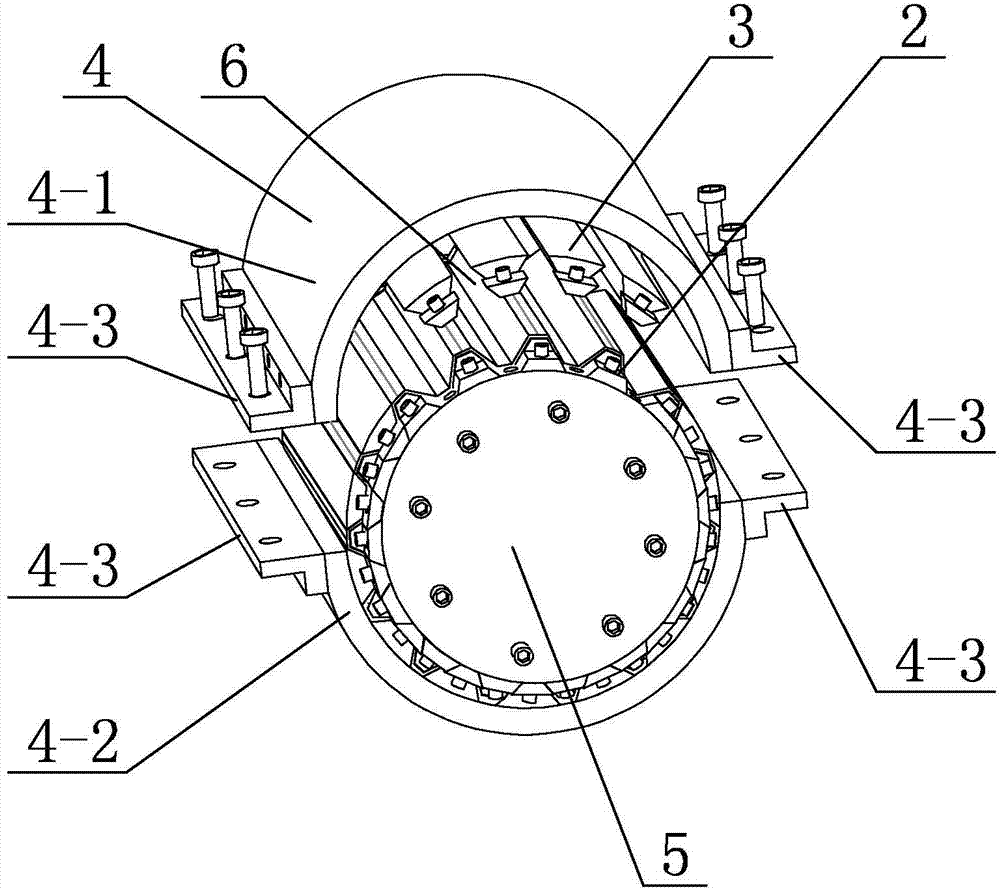
[0031] Specific implementation mode one: combine figure 1 , figure 2 , image 3 , Figure 4 , Figure 5 , Image 6 , Figure 7 , Figure 8 , Figure 9 and Figure 14 Describe this embodiment, in this embodiment it comprises stem 1, mold clamping fixture 4, two end caps 5, a plurality of inner core strip bodies 2 and a plurality of outer core strip bodies 3, and described stem post 1 is split The two end caps 5 are detachably connected to the top surface and the bottom surface of the stem 1 respectively, and a plurality of inner core strips 2 and a plurality of outer core strips 3 alternate along the axial direction of the stem 1 Arranged on the outer circumference of the core column 1, there is a gap between each inner core bar body 2 and its adjacent outer core bar body 3, the mold clamping fixture 4 is cylindrical, and the mold clamping fixture 4 is set On the stem 1 with a plurality of inner core strips 2 and a plurality of outer core strips 3, the inner wall of t...

Example Embodiment

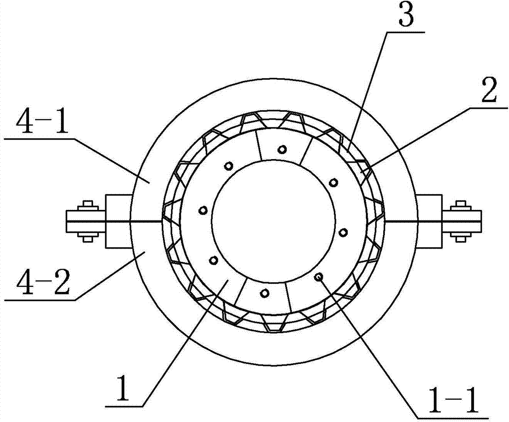
[0032] Specific implementation mode two: combination figure 2 , Figure 7 , Figure 8 and Figure 14 To illustrate this embodiment, in this embodiment, the top surface and the bottom surface of the stem 1 are respectively processed with end cap connection holes 1-1; the outer surface of the stem 1 is uniformly processed in multiple rows along its radial direction The first core bar connection hole 1-2. In this embodiment, the connection hole 1-1 of the end cap is to realize the connection of the stem 1 and the end cap 5; Connection of a plurality of outer core strip bodies 3 . In this embodiment, the end cap 5 is also processed with connection holes corresponding to the end cap connection holes 1-1, and the end cap 5 and the stem 1 are detachably connected by screws, thereby realizing the end cap 5 and the stem. 1 is effectively connected to ensure the basic framework of the stem 1. Other unmentioned components and connections are the same as those in the first embodime...

Example Embodiment

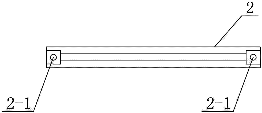
[0033] Specific implementation mode three: combination figure 1 , image 3 and Figure 4 Describe this embodiment. In this embodiment, when the inner core strip body 2 is placed vertically, the cross section of the inner core strip body 2 in the horizontal direction is trapezoidal, and the inner core strip body 2 is processed with a The first core strip connection hole 1-2 corresponds to the second core strip connection hole 2-1. When the inner core strip body 2 is detachably connected to the core column 1 through the second core strip connection hole 2-1, the inner core strip The width of one end surface of the strip body 2 close to the stem 1 is gradually reduced to the width of the other end surface far away from the stem 1 . In this embodiment, the width of the end surface of the inner core strip body 2 on the side close to the stem 1 on the inner core strip body 2 gradually decreases to the width of the end surface of the inner core strip body 2 on the side away from th...


PUM


Abstract

The invention discloses an assembling mold for all-composite corrugated sandwich cylindrical shells and relates to the assembling mold with an aim to overcome shortcomings about lack of special mold during production of existing all-composite corrugated sandwich cylindrical shells, skins and plates are not easy to be connected during production of other sandwich cylindrical shell, filament winding cannot be avoided, and the production process is complicated and not easy to for mass production. A core column is a split-type hollow column, two end caps are respectively detachably connected to the top surface and the bottom surface of the core column, multiple inner core strips and multiple outer core strips are alternatively arranged on the outer periphery of the core column along the axial direction of the core column, each inner core strip and each outer core strip are arranged at an interval, and a clamping fixture sleeves the core column provided with the inner core strips and the outer core strips. The cylindrical shells different in thickness can be produced, and mass production can be realized. The assembling mold is used for production of the all-composite corrugated sandwich cylindrical shells.

Description

technical field [0001] The invention specifically relates to a composite mold for a corrugated sandwich cylindrical shell made of full composite material. Background technique [0002] With the development of aviation, aerospace and various engineering fields, the lightweight design of the structure is particularly important. The sandwich structure has excellent mechanical properties such as high specific strength and specific modulus. Currently, the cylindrical shells used for large aerospace structures are mostly Grid-reinforced structure, including grid-reinforced structure without skin, grid-reinforced structure with inner skin, grid-reinforced structure with outer skin, and grid-reinforced structure with inner and outer skin, the preparation process is complicated. For composite materials Cylindrical shells are not easy to achieve an effective connection between the skin and the panels. [0003] For composite reinforced cylindrical shells, the more mature processes are...

Claims


Application Information

Patent Timeline
IPC IPC(8): B29C70/46B29C70/54B29C33/42
CPCB29C33/42B29C70/46B29C70/54
Inventor 冯丽娜熊健郑伟杨金水吴林志
Owner HARBIN INST OF TECH
Why Eureka
Try Eureka