Method for easily replacing igniter of sintering machine

A replacement method and igniter technology, applied in the furnace type, furnace, lighting and heating equipment, etc., can solve the problems of limited operating area, easy cracks, falling off, etc., to achieve the effect of ensuring installation quality and maintenance time

Inactive Publication Date: 2014-07-02
LAIWU IRON & STEEL GRP
View PDF5 Cites 1 Cited by
  • Summary
  • Abstract
  • Description
  • Claims
  • Application Information

AI Technical Summary

Problems solved by technology

The operating area of ​​the two cranes is very limited, there are only two spans at the tail, and they cannot enter other areas) The traditional crane installation is adopted, and the igniter at the nose cannot be used.
Moreover, the refractory material inside the igniter is prone to major equipment failures such as cracks or overall shedding when receiving external forces such as hoisting

Method used


Image

  • Method for easily replacing igniter of sintering machine
  • Method for easily replacing igniter of sintering machine
  • Method for easily replacing igniter of sintering machine

Examples


Embodiment Construction

[0028] The present invention will be further described in detail with the accompanying drawings and specific embodiments.

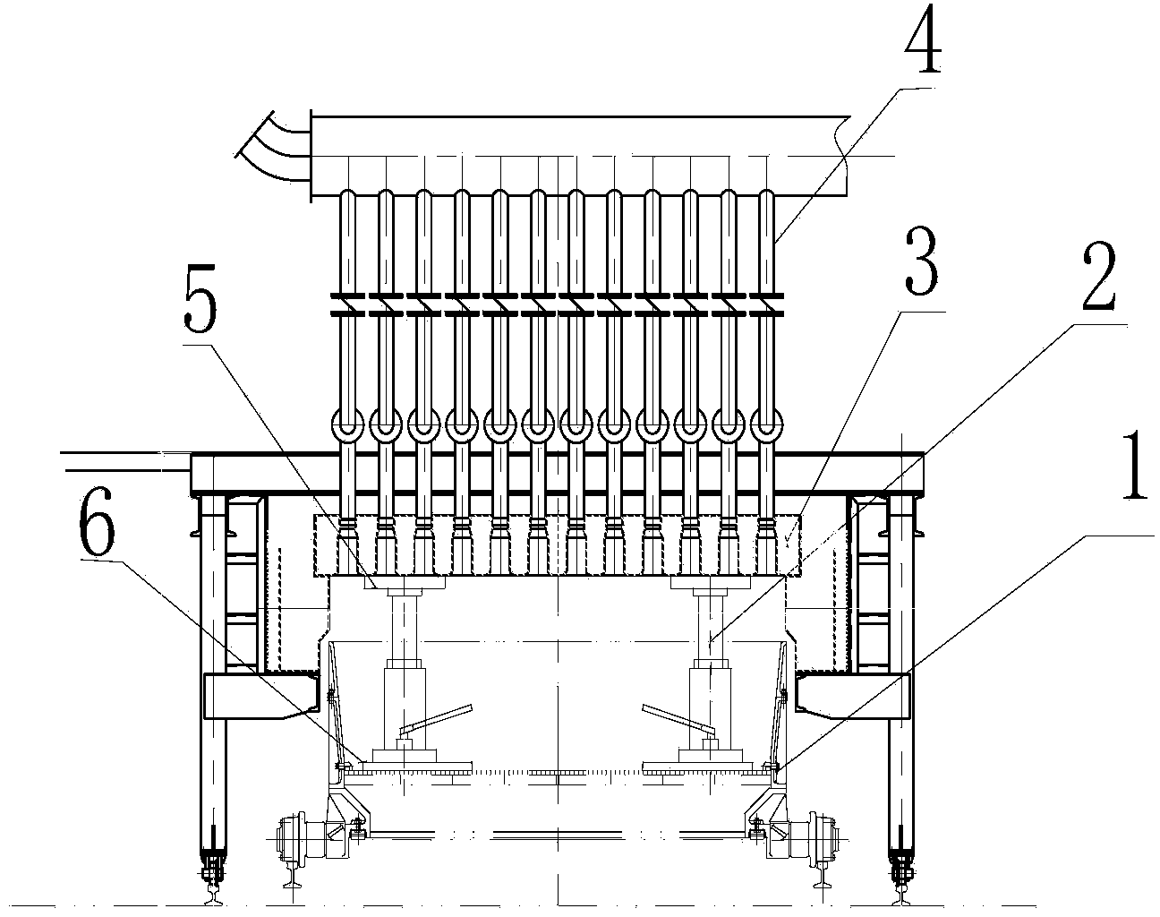
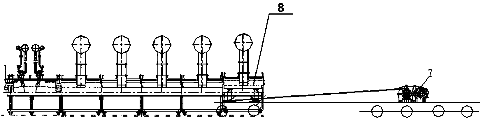
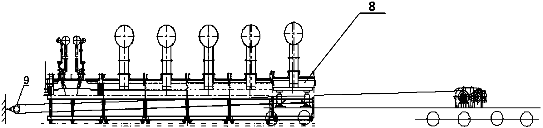
[0029] Such as figure 1 , figure 2 and image 3 Shown, a sintering machine igniter simple replacement method, the method includes the following steps:

[0030] Preparation

[0031] 1) Reinforcement of igniter 8: In order to ensure the overall stability of the new igniter without deformation during hoisting, the igniter 8 should be reinforced, specifically, 25# channel steel should be welded vertically and horizontally at appropriate positions around the new igniter, and the old igniter should also be reinforced. Corresponding reinforcement;

[0032] 2) Preparation of hoisting tools: The following main hoisting tools should be prepared: one 50T winch, four 32T short-body screw jacks, two 300*3000mm H-shaped steel pieces, four 500*500*50mm steel plates, and 100 meters of 25MM diameter steel wire rope;

[0033] 3) Preparation of the trolley: Remove the...


PUM


Abstract

The invention discloses a method for easily replacing an igniter of a sintering machine. According to the method, an old igniter is jacked through a jack and is pulled out through a winch, and then a new igniter is installed in place according to the same method. The method is simple, installation is convenient, installation quality is reliable, and overhauling time is short.

Description

technical field [0001] The present invention relates to the maintenance field of sintering machine equipment, in particular, the present invention relates to a simple replacement method for a sintering machine igniter. Background technique [0002] The igniter is the key equipment of the sintering machine, and its installation quality directly affects the quality and output of sintering ore. The igniter is not only bulky but also heavy. The new igniter has an assembled weight of 60 tons. Compared with other sintering equipment, it is difficult to replace. According to the layout of the cranes on the platform of the sintering machine body (there are two cranes, one is 16 tons and the other is 32 tons. The operating area of ​​the two cranes is very limited , there are only two spans at the tail and cannot enter other areas) the traditional driving installation is adopted, but the igniter at the nose cannot be used. Moreover, the refractory material inside the igniter is pro...

Claims


Application Information

Patent Timeline
Patent Type & Authority Applications(China)
IPC IPC(8): F27B21/08
Inventor 高志强
Owner LAIWU IRON & STEEL GRP
Why Eureka
Try Eureka