

Pneumatic tire
一种充气轮胎、胎面花纹的技术,应用在轮胎零部件、轮胎胎面/胎面花纹、运输和包装等方向,能够解决接地面积减少、接地压力增高、易产生异常噪音等问题,达到提高制动性能、抑制偏磨损或噪音的产生的效果
Active Publication Date: 2015-06-24
TOYO TIRE & RUBBER CO LTD
View PDF12 Cites 0 Cited by
- Summary
- Abstract
- Description
- Claims
- Application Information
AI Technical Summary
Problems solved by technology
[0003] However, if the number of sipes provided on the ground contact portion is increased, the rigidity of the ground contact portion decreases, and the ground contact portion is excessively crushed, so the ground contact area decreases, and the ground contact pressure locally increases, thereby melting Ice on icy and snowy roads makes it easy to form a water film, and there is a problem of reduced braking performance on icy and snowy roads
In addition, if the degree of crushing of the ground contact portion increases, there is a problem that the ground contact portion is prone to partial wear, or when the crushed ground contact portion is separated from the road surface and returns to its original shape, the ground contact portion rubs against the road surface and is prone to wear. abnormal noise
Method used
View moreImage
Smart ImageViewing Examples

Examples
Embodiment 1
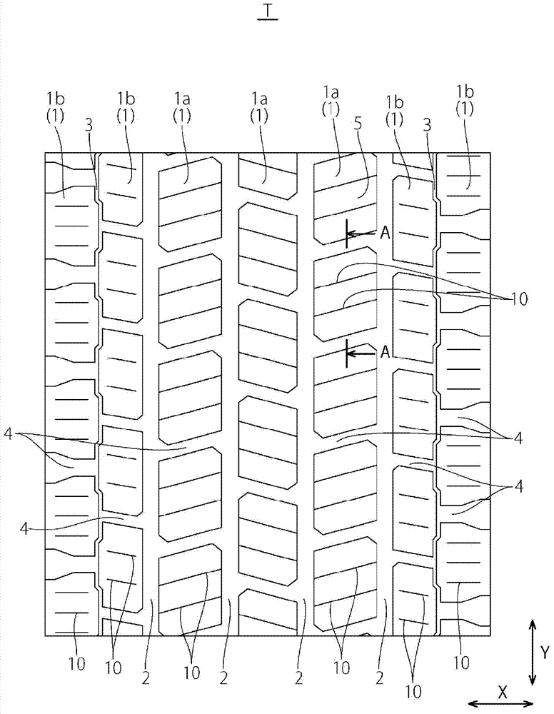
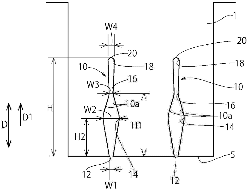
[0062] Example 1 is, in figure 1 In the tread pattern T shown, it will be as figure 2 The sipe 10 having the shown cross-sectional shape is formed on the entire block of the tire. The depth H of the sipe 10, the length H1 from the opening end 12 to the constricted portion 16 in the sipe depth direction D, the length H2 from the opening end 12 to the first wide portion 14 in the sipe depth direction D, Various dimensions of the width W1 of the opening end 12 of the sipe 10, the groove width W2 of the first wide portion 14, the groove width W3 of the constricted portion 16, and the groove width W4 of the second wide portion 18 As shown in Table 1.
Login to View More PUM
 Abstract
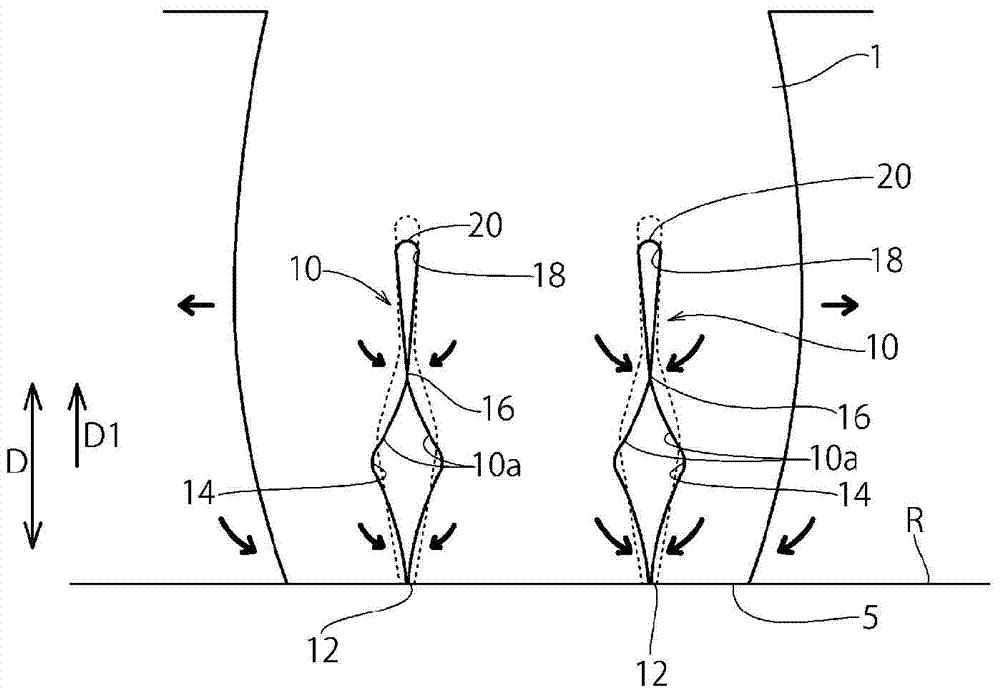
In a pneumatic tire, a sipe formed in a land portion includes a first large width portion having a larger groove width than an opening end formed on a surface of a tread, a neck portion having a smaller groove width than the first large width portion, and a second large width portion having a larger groove width than the neck portion which are disposed in this order on a depth side in a sipe depth direction.
Description
technical field [0001] The present invention relates to a pneumatic tire provided with a tread pattern having a ground contact portion in which sipes are formed. Background technique [0002] Conventionally, for example, in studless tires, incisions called sipes are provided on the ground contact parts such as blocks or ribs, and the edge effect based on the sipes enables stable driving. On icy and snowy roads with a low coefficient of friction. As such sipes, there are known so-called three-dimensional sipes that change the shape of the sipe in the depth direction, linear sipes that open in a straight line on the tread surface, or sipes that open in a wave shape. Wave-shaped sipes are disclosed in, for example, JP-A-2011-157011, JP-A-8-197915, and JP-A-2009-160986. [0003] However, if the number of sipes provided on the ground contact portion is increased, the rigidity of the ground contact portion decreases, and the ground contact portion is excessively crushed, so the ...
Claims
Login to View More Application Information
Patent Timeline
 Patent Type & AuthorityApplications(China)
IPC IPC(8): B60C11/04
CPCB60C11/11B60C11/1218B60C11/1281B60C2011/1209B60C2011/1254
Inventor梶真一
OwnerTOYO TIRE & RUBBER CO LTD