Pipeline hose

A pipeline type and hose technology, which is applied in the direction of hoses, pipeline layout, pipes/pipe joints/fittings, etc. It can solve the problems of decreased strength of the foamed resin layer, damage to the shape retention of the hose, and a decrease in the heat insulation performance of the hose, etc. Achieve the effect of suppression of ventilation resistance, maintenance of shape retention, and simple structure

Inactive Publication Date: 2015-08-19
TOTAKU IND INC
View PDF9 Cites 0 Cited by
  • Summary
  • Abstract
  • Description
  • Claims
  • Application Information

AI Technical Summary

Problems solved by technology

[0006] However, in the duct-type hose described above, noise can be attenuated only by the film portion on the inner peripheral surface side of the foamed resin layer and the sound-absorbing hole portion of the foamed resin layer, and high sound-absorbing performance cannot be expected at all.
In particular, when reducing the number of sound-absorbing holes or reducing the size of the sound-absorbing holes to reduce the proportion of the sound-absorbing holes in the foamed resin layer as a whole, the sound-absorbing performance will decrease. On the contrary, when increasing the number of sound-absorbing holes or increasing When the size of the sound-absorbing holes is increased to increase the ratio of the sound-absorbing holes in the entire foamed resin layer to improve the sound-absorbing performance, the strength of the foamed resin layer will decrease, the shape retention of the hose will be impaired, and there will be heat insulation of the hose. Paradox that performance is also degraded

Method used


Image

  • Pipeline hose
  • Pipeline hose
  • Pipeline hose

Examples


no. 1 approach

[0036] The ducted hose of the first embodiment of the present invention is connected to the supply and exhaust ports of refrigeration and heating devices such as houses or buildings, or connected to the supply and discharge ports of ventilation devices, and is used as a connection to these air conditioners. For exhaust.

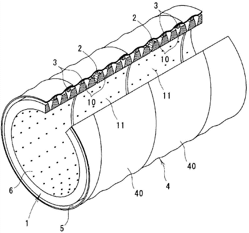
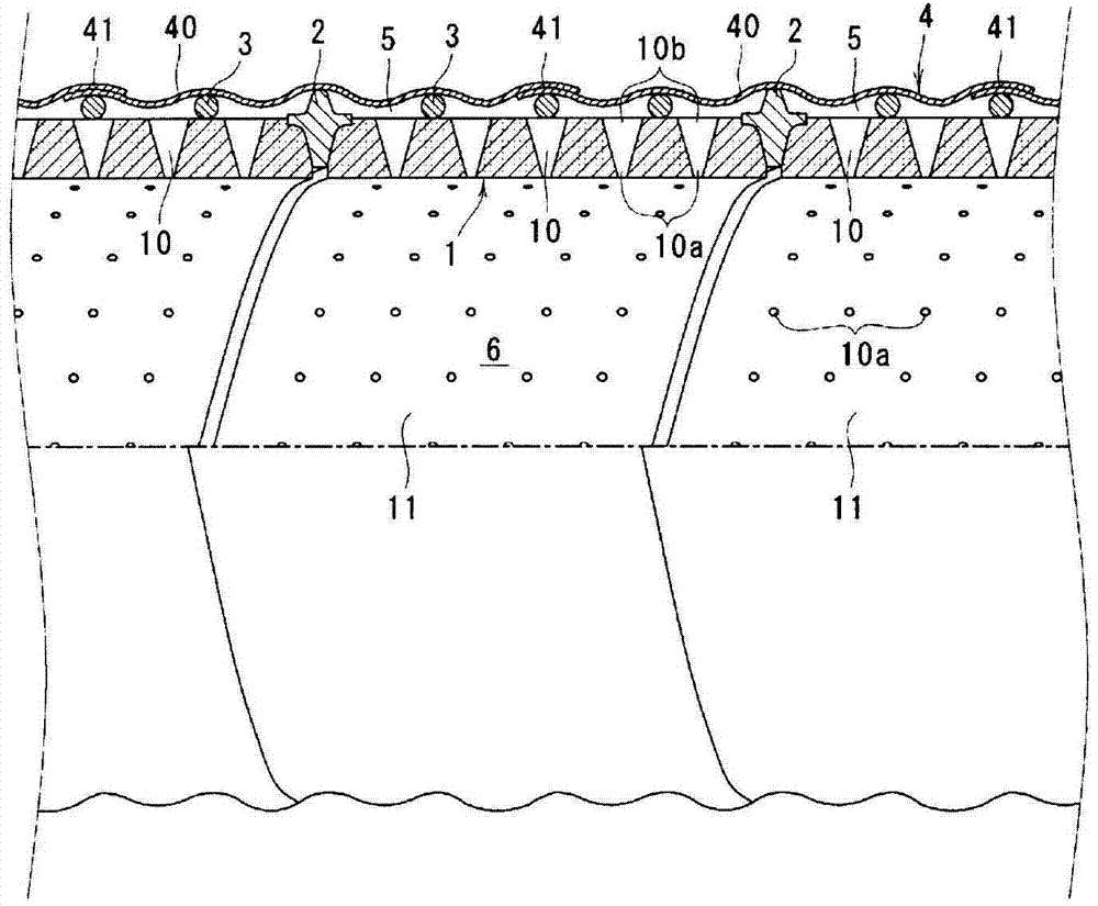
[0037] The pipeline hose such as Figure 1 to Figure 3 As shown in FIG. , thereby forming a structure in which a void portion 5 is formed between the outer peripheral surface of the inner layer 1 and the inner peripheral surface of the outer layer 4 . The duct-type hose has flexibility as a whole, and allows gas (air for supplying and exhausting air) to flow through the internal space 6 surrounded by the inner peripheral surface of the inner layer 1 .

[0038]In the inner layer 1, a plurality of sound-absorbing holes 10 having a substantially V-shaped cross-section are formed penetrating in the radial direction of the hose at appropriate intervals in the ax...

no. 2 approach

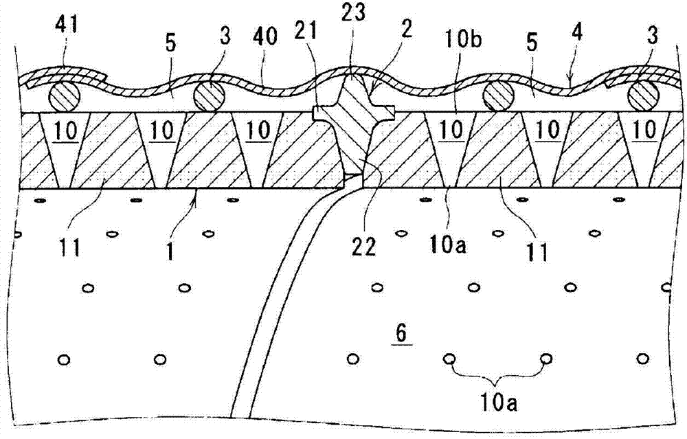
[0055] The pipeline type hose of the second embodiment of the present invention such as Figure 6 to Figure 8 As shown, the reinforcing core material 2 is formed in a substantially T-shaped cross section having a horizontal piece 21 and a vertical piece 22 . Furthermore, an elastic spacer 50 for pushing the outer layer 4 outward in the hose radial direction is attached to the outer peripheral surface of the horizontal piece 21 of the reinforcing core material 2 .

[0056] The elastic spacer 50 is made of, for example, foamed polyethylene resin, and its width is wider than that of the transverse sheet 21 of the reinforcing core material 2, and is formed in a roughly rectangular cross-section with a thickness of about 3 mm, covering and concealing the transverse sheet 21. , and wound into a helical shape along the outer peripheral surface of the horizontal piece 21. In addition, the joint portion 41 between the adjacent edge portions of the soft resin sheet 40 in the outer laye...


PUM


Abstract

Provided is a duct hose wherein, even with a simple structure, the acoustic absorption performance is remarkably improved. In the duct hose, an outer layer (4) composed of a cylindrical soft resin layer is provided on the outer peripheral surface of an inner layer (1) composed of a cylindrical foamable resin layer via a reinforcing core element (2), so that a clearance portion (5) is formed between the outer peripheral surface of the inner layer (1) and the inner peripheral surface of the outer layer (4); and a plurality of acoustic absorption holes (10) are formed in the inner layer (1), and an inner space (6) communicates with the clearance portion (5) via the acoustic absorption holes (10), so that a noise propagating through the inner space (6) is introduced to the clearance portion (5).

Description

technical field [0001] The present invention relates to a ducted hose used for air supply and exhaust of air-conditioning equipment in houses, buildings, and the like. Background technique [0002] Conventionally, in ducted hoses for air supply and exhaust, noise reduction measures have been taken to attenuate the noise generated from the air supply source as much as possible inside the hose and prevent the noise from being transmitted to the room. [0003] As such a duct-type hose, there is known a structure in which, for example, as disclosed in Patent Document 1, there is a cylindrical foamed resin layer provided with a plurality of sound-absorbing holes, and a structure made of non-woven fabric or the like is used. The air-permeable film covers the inner opening ends of the plurality of sound-absorbing holes in the foamed resin layer, and guides the noise transmitted in the inner space of the hose from the vent holes of the film to the sound-absorbing holes of the foamed...

Claims


Application Information

Patent Timeline
Patent Type & Authority Patents(China)
IPC IPC(8): F24F13/02F16L11/12F16L55/02
CPCF16L55/05F24F13/0263F24F2221/22F24F2013/242F24F2013/245F16L55/02781
Inventor 吉田龙志菊森康博町野达也中俣庆治南一行月江洋一郎松下史和
Owner TOTAKU IND INC
Why Eureka
Try Eureka