
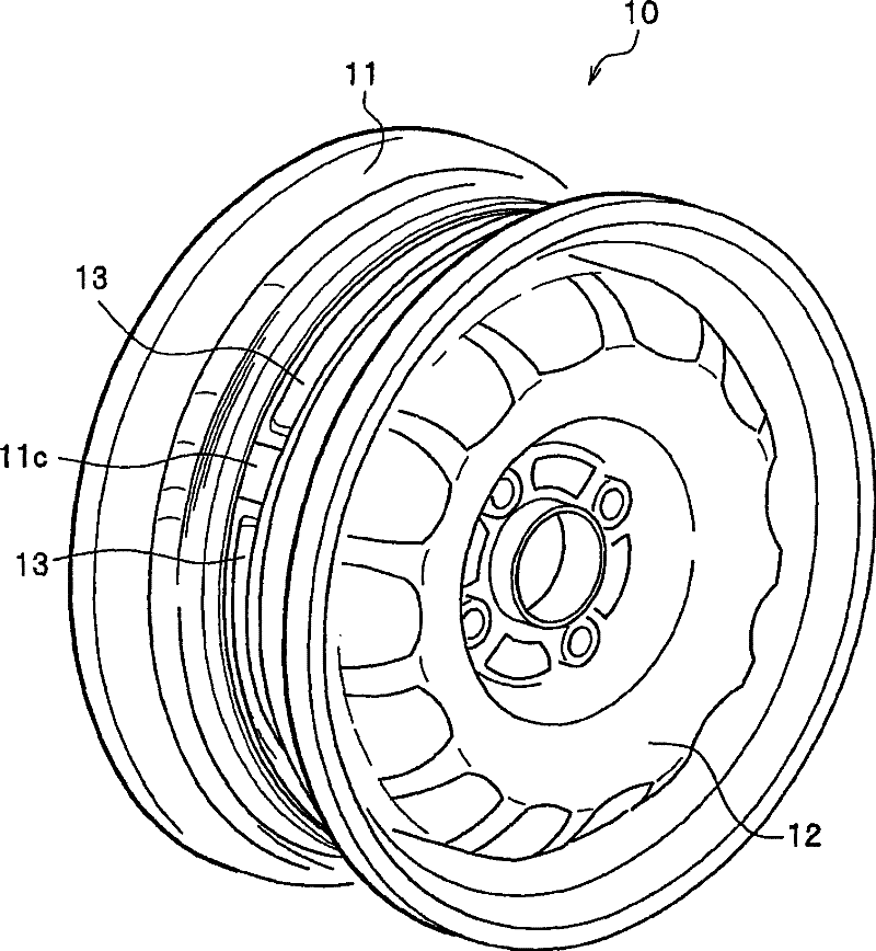
Vehicle wheel

A vehicle and wheel technology, applied in the direction of wheels, vehicle components, rims, etc., can solve the problems of wheel weight, volume increase and decrease of auxiliary air chamber, and increase of centrifugal force of auxiliary air chamber components, so as to suppress volume fluctuation, improve surface rigidity, suppress Depressed effect

Active Publication Date: 2011-07-13
HONDA MOTOR CO LTD +1
View PDF1 Cites 0 Cited by
  • Summary
  • Abstract
  • Description
  • Claims
  • Application Information

AI Technical Summary

Problems solved by technology

[0004] However, this existing vehicle wheel has a problem
That is, there is a problem that, in a wheel in which the vertical wall is formed so as to stand up from the wheel well, it is necessary to combine a plurality of bulkheads and cover members with high precision by welding, bonding, embedding, and coupling in order to maintain airtightness. , when consideration is given to airtightness assurance, manufacturing man-hours, and increased manufacturing costs, it is not suitable for mass production
[0006] However, in the case of using resin as a material, compared with the case of using metal, since the surface rigidity of the wall material constituting the sub-air chamber is lower, in the tire air chamber, the positive side and the negative side are generated by air column resonance. When the air pressure fluctuates sideways and alternately, the volume of the sub-air chamber slightly increases or decreases, and the sound-absorbing performance as a Helmholtz resonator may not be sufficiently obtained.
[0007] In this case, it is considered to increase the rigidity by increasing the thickness of the above-mentioned wall material, but when the wall thickness of the wall material increases, the weight of the sub-air chamber member increases, and the centrifugal force acting on the sub-air chamber member also increases. The members for fixing the sub-air chamber members to the wheel wells also need to increase in strength, resulting in heavier and heavier vehicle wheels.

Method used


Image

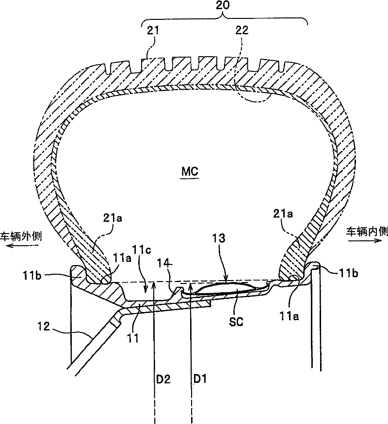
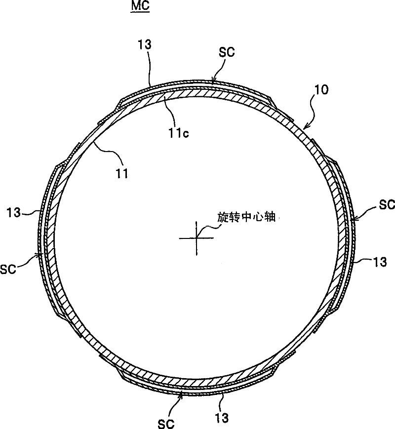
  • Vehicle wheel
  • Vehicle wheel
  • Vehicle wheel

Examples


no. 2 example

[0135] (Auxiliary air chamber of the first modified example)

[0136] Fig. 9 (A), (B) is the figure that shows the sub-air chamber member of the second embodiment (the first modified example of the sub-air chamber); Expanded top view; FIG. 9(B) is a sectional view taken along the line E-E in FIG. 9(A).

[0137] In the sub-air chamber member 13B of the first modified example, for example, four longitudinal grooves (grooves, creases) 31 are formed on the bottom plate 25a of the sub-air chamber member 13A and extend in the wheel circumferential direction while being concave toward the sub-air chamber SC side, and For example, 15 horizontal grooves (grooves, creases) 32 are formed, which are recessed toward the side of the sub air chamber SC and extend in the wheel width direction.

[0138] In this way, the longitudinal groove 31 and the transverse groove 32 are provided on the shallow convex curved bottom plate 25a in the radial section of the wheel, whereby when the internal pr...

no. 3 Embodiment

[0143] (Auxiliary air chamber of the second modified example)

[0144] Fig. 9 (C), (D) is the figure that shows the auxiliary air chamber member of the 3rd embodiment (the second modified example of the auxiliary air chamber); Expanded top view; FIG. 9(D) is a sectional view taken along the direction F-F in FIG. 9(C).

[0145] In the sub-air chamber member 13B' of the second modified example, a plurality of longitudinal grooves 31 are formed on both the bottom plate 25a and the upper plate 25b of the sub-air chamber member 13A, and are recessed toward the side of the auxiliary air chamber SC and extending in the wheel circumferential direction. A plurality of lateral grooves 32 are recessed toward the side of the sub air chamber SC and extend in the wheel width direction.

[0146] In this way, the longitudinal groove 31 and the transverse groove 32 are provided on both the shallow convexly curved bottom plate 25a and the strongly convexly curved upper plate 25b in the wheel r...

no. 4 Embodiment

[0149] (Auxiliary air chamber of the third modified example)

[0150] Figure 10A It is a developed plan view of the sub-air chamber member of the fourth embodiment (the third modified example of the sub-air chamber) viewed from the radially outer side of the wheel; FIG. 10(B) is a developed plan view of the sub-air chamber member viewed from the radially inner side of the wheel; Fig. 10(C) is a sectional view taken along the line K-K in Fig. 10(B).

[0151] In the sub-air chamber member 13C of the fourth embodiment, a plurality of longitudinal grooves 31 concave toward the sub-air chamber SC side and extending in the wheel circumferential direction are formed on the bottom plate 25a of the sub-air chamber member 13A, and a plurality of longitudinal grooves 31 concave toward the auxiliary chamber SC are formed. The lateral groove 32 extending in the wheel width direction on the side SC of the air chamber further partially forms a deep depression from the side of the bottom plat...


PUM


Abstract

The present invention provides a vehicle wheel, wherein a sub air chamber (13C) is provided with a plurality of grooves (31) concavely facing the sub air chamber (SC) side and extending along wheel circumferential direction, and a plurality of grooves (32) concavely facing the sub air chamber (SC) side and extending along wheel width direction on a bottom plate (25a) of a sub air chamber component (13A), in addition, a fovea is formed locally from the bottom plate (25a) to an upper plate (25b), and an upper butt-jointing portion (binding portion) (33A) is formed on several positions of the fovea bottom for jointing the bottom plate (25a) and the upper plate (25b). In the sub air chamber (13C) of the transfiguration embodiment, in the center of the wheel width direction, at least one of the bottom plate (25a) and the upper plate (25b) of the sub air chamber (13) is formed with grooves (31) in a direction crossed with a first longitudinal wall surface (15) and a second longitudinal wall surface (16) extending in a row along the circumferential direction of the wheel, and the butt-jointing portion (33A) is divided into eleven parts with equal interval.

Description

technical field [0001] The present invention relates to a vehicle wheel for reducing noise accompanying air column resonance (cavity resonance) in a tire air chamber. Background technique [0002] Vehicle wheels that reduce noise associated with air column resonance in a tire air chamber are known. Generally, air column resonance generated in an air chamber of a tire (hereinafter, referred to as a "tire air chamber") is a main cause of road noise of an automobile. Air column resonance is a phenomenon in which random vibration transmitted from the road surface to the tire causes the air in the tire air chamber to vibrate, resulting in a resonance phenomenon near the air column resonance frequency of the tire air chamber and resonance sound. [0003] (Japanese) Unexamined Patent Publication No. 2004-90669 discloses a vehicle wheel for reducing noise accompanying the air column resonance. This vehicle wheel has a plurality of sub-air chambers in the circumferential direction ...

Claims


Application Information

Patent Timeline
Patent Type & Authority Patents(China)
IPC IPC(8): B60B19/00B60B21/00
Inventor 柏井干雄神山洋一石井克史山本修平早川哲央神尾健一
Owner HONDA MOTOR CO LTD
Learn More