Threaded lift table

A technology of threaded lifting and threaded holes, applied in the direction of lifting devices, etc., can solve the problems of low adjustment accuracy, poor linearity of high and low motion, complex structure, etc., and achieve the effect of low processing technology requirements and reduced processing requirements

Active Publication Date: 2017-03-15
SHANGHAI INST OF OPTICS & FINE MECHANICS CHINESE ACAD OF SCI
View PDF5 Cites 0 Cited by
  • Summary
  • Abstract
  • Description
  • Claims
  • Application Information

AI Technical Summary

Problems solved by technology

[0002] In the optical path adjustment, the center height is generally adjusted by the lifting rod seat; one kind of lifting rod seat is directly adjusted by hand, without a drive unit, and the adjustment accuracy is low; the other kind of lifting rod is adjusted by thread, and the threaded rod is also a load The threaded rod is guided by the key, the linearity of the up and down motion is poor, and the stability is low; at the same time, the precision-driven lifting platform has units such as precision guide rails and drives, and the structure is complex

Method used


Image

  • Threaded lift table
  • Threaded lift table
  • Threaded lift table

Examples


Embodiment Construction

[0026] The present invention will be further described below in conjunction with the accompanying drawings and specific examples, but not as a limitation to the present invention.

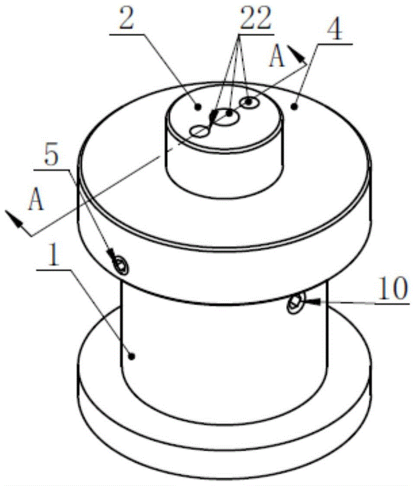
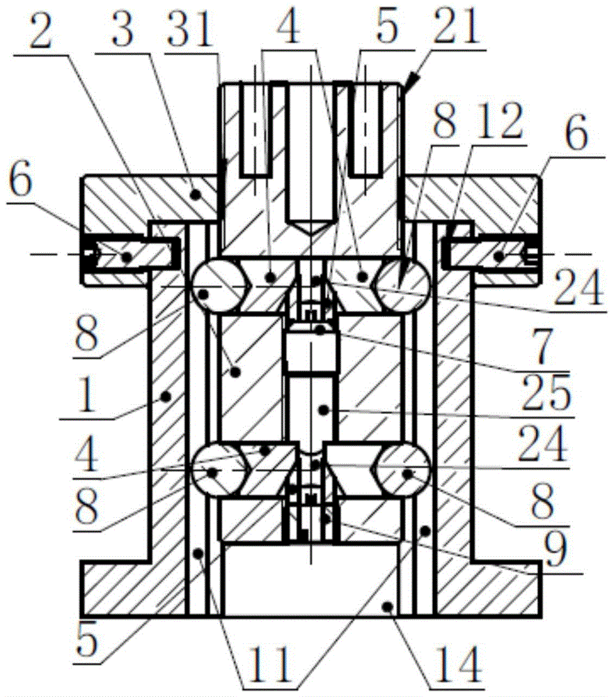
[0027] like figure 1 , 2 As shown, it can be seen from the figure that the threaded lifting platform of the present invention comprises a lifting rod seat 1, a lifting screw rod 2, a lifting screw cover 3, a top column 4, a top tightening block 5, a fixed rotation screw 6, a set screw 7, four A steel ball 8, a pressure ring 9 and a fastening screw 10;

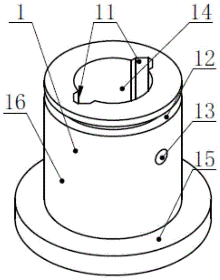
[0028] The lifting rod base 1 is a cylinder with a middle through hole 14, in which there are two relative top-to-bottom V-shaped chute 11, the cylinder of the lifting rod base 1 There is an annular groove 12 on the outer cylindrical surface 16 at the port, and there are threaded holes 13 and lower bottom steps 15 on the outer cylindrical surface 16;

[0029] The lifting screw 2 is a cylinder, the outer circle of the upper end has an external thr...


PUM


Abstract

The invention relates to a thread lifting platform. The thread lifting platform comprises a lifting rod seat, a lifting screw rod, a lifting screw cover, a support pillar, an abutting block, a fixing rotating screw, a stopper screw, steel balls, a pressing ring and a tightening screw. According to the thread lifting platform, the lifting screw cover adjusts the lifting screw rod and achieves the up-and-down motion through the guide of the steel balls, the abutting block with elasticity enters a V-shaped sliding groove through the support pillar abutting against the steel balls, the elasticity of the abutting block makes up for the error of the V-shaped sliding groove, the steel ball is made to contact with the V-shaped sliding groove tightly, and the arrangement of the two pairs of up-and-down steel balls guarantee the movement stability of the lifting screw rod in the lifting rod seat. The probation shows that the screw lifting platform has the advantages that the structure is simple, adjustment is convenient, and stability and reliability are possessed.

Description

technical field [0001] The invention relates to an adjustment mechanism that supports small devices for small movements up and down. It is mainly used to support optical components. The height of the center of various components in the optical path is finely adjusted through this lifting mechanism. The adjustment is accurate and the stability is good; Background technique [0002] In the optical path adjustment, the center height is generally adjusted by the lifting rod seat; one kind of lifting rod seat is directly adjusted by hand, without a drive unit, and the adjustment accuracy is low; the other kind of lifting rod is adjusted by thread, and the threaded rod is also a load The table, the threaded rod is guided by the key, the linearity of the up and down motion is poor, and the stability is low; at the same time, the precision-driven lifting platform has units such as precision guide rails and drives, and the structure is complex. Contents of the invention [0003] Th...

Claims


Application Information

Patent Timeline
Patent Type & Authority Patents(China)
IPC IPC(8): B66F13/00
CPCB66F13/00
Inventor 杜李峰朱健强杨晓伟刘志刚庞向阳
Owner SHANGHAI INST OF OPTICS & FINE MECHANICS CHINESE ACAD OF SCI
Why Eureka
Try Eureka