Jacking system for fixing scaffold

A scaffolding and jacking technology, which is applied to scaffolding accessories, house structure support, house structure support, etc.

Active Publication Date: 2015-06-24
CHINA METALLURGICAL CONSTR ENG GRP
View PDF7 Cites 1 Cited by
  • Summary
  • Abstract
  • Description
  • Claims
  • Application Information

AI Technical Summary

Problems solved by technology

[0003] The purpose of the present invention is to provide a jacking system for fixing scaffolding in order to solve the problems of uneven stress on steel pipes and vertical poles of existing scaffolding, easy deviation of vertical poles and only satisfying vertical downward force

Method used


Image

  • Jacking system for fixing scaffold
  • Jacking system for fixing scaffold
  • Jacking system for fixing scaffold

Examples


Embodiment 1

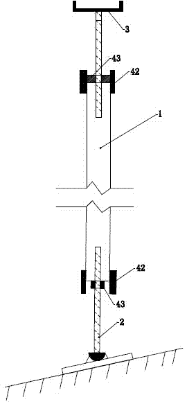
[0027] Such as image 3 As shown, when the base surface of the scaffold to be erected is an inclined plane, and the length of the steel pipe 1 is not enough, a vertical pole 2 is vertically arranged at both ends of the steel pipe 1, and the vertical pole 2 at both ends is fixed by an adjustable mounting support 4 . Wherein, the bottom end of the vertical rod 2 positioned at the lower end is fixed to the anti-skid bottom bracket (not shown in the figure) arranged on the slope. The anti-skid bottom bracket is composed of a base plate and a bump fixedly connected to the upper end of the base plate. A downwardly concave spherical surface is arranged on the top of the bump; Cap, the connecting cap fits with the spherical surface in the non-slip bottom bracket. The connection structure between the upright bar 2 and the anti-skid bottom bracket not only ensures the stability of the upright bar, but also prevents the upright bar from moving or even hanging in the air when the fr...

Embodiment 2

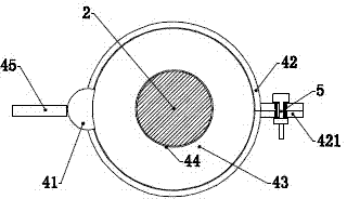
[0029] Such as Figure 4 As shown, when the base surface of the scaffolding needs to be erected as a plane, the steel pipe 1 is vertically installed on the wooden block (not shown in the figure) installed on the ground, and an adjustable mounting support is set on the top of the steel pipe 1 4. Match a vertical rod 2 with the positioning nut 43 in the adjustable mounting bracket 4 and fasten it. During the fastening process, the height of the scaffold can be adjusted by moving up and down the fastening position of the vertical rod 2 and the positioning nut 43 .

Embodiment 3

[0031] Such as Figure 5 As shown, when the base surface for scaffolding needs to be set up as a plane and the steel pipe is not long enough, adjustable mounting supports 4 can be installed at the upper and lower ends of the steel pipe 1, and an adjustable mounting support 4 can be installed in the middle of each adjustable mounting support 4 A vertical pole 2 and a supporting plate 3 are arranged vertically. Wherein, the supporting plate 3 positioned at the lower end of the steel pipe 1 is engaged with a wooden spacer block (not shown in the figure) installed on the ground. In this case, adjusting the height of the scaffold is achieved by rotating the adjustable mounting supports 4 at the upper and lower ends, and then moving up and down the vertical rod 2 and the fastening position of the positioning nut 43 in the adjustable mounting supports 4 .


PUM


Abstract

The invention discloses a jacking system for fixing a scaffold. The jacking system for fixing the scaffold comprises a steel tube, vertical rods and supporting plates, wherein the steel tube and the vertical rods are vertically arranged, and the supporting plates are mounted at the tail ends of the vertical rods. The vertical rods are provided with threads, and one ends of the vertical rods are sleeved with the steel tube. The jacking system for fixing the scaffold further comprises adjustable mounting supports which are mounted at the upper end and / or the lower end of the steel tube. Each adjustable mounting support comprises a mounting cylinder, two pinch plates which are symmetrically arranged on the two sides of the mounting cylinder and are semicircular, and a set screw nut which is connected with the mounting cylinder and located in the pinch plates. The pinch plates are rotatably connected to the left sides and the right sides of the mounting cylinders, the tail ends of the pinch plates can be fixedly connected through bolts, and every two pinch plates are closed to be in a cylinder shape to be used for clamping the steel tube. The set screw nuts are matched with the steel tube, and center holes of the set screw nuts are connected with the vertical rods through the threads. According to the jacking system for fixing the scaffold, the stress of the steel tube and the stress of the vertical rods are located on the same central axis, the vertical rods, the steel tube and the supporting plates are connected to form a whole, and the jacking system can be widely applied to supporting different formworks.

Description

technical field [0001] The invention relates to the field of scaffold erection, in particular to a jacking system for fixing a scaffold. Background technique [0002] Conventional scaffold jacking is mainly used for the transmission of vertical downward force. There are two problems in the application: 1. The diameter of the jacking pole is smaller than the inner space of the steel pipe, so the force cannot be completely guaranteed to be on the axis of the pole. In the case of unreasonable installation, there will also be a phenomenon of vertical pole tilting; 2. The jack screw is directly inserted into the steel pipe, failing to form a whole with the steel pipe, and can only meet the conventional vertical downward force. When the hyperboloid and side formwork need to be reinforced, the deviation is serious and unstable; 3. The length of the pole and the steel pipe is fixed, and the overall length of the steel pipe and the pole after installation cannot be adjusted accordin...

Claims


Application Information

Patent Timeline
Patent Type & Authority Applications(China)
IPC IPC(8): E04G5/06E04G5/02
Inventor 何俨杨洋邱长林
Owner CHINA METALLURGICAL CONSTR ENG GRP
Why Eureka
Try Eureka