Combustion chamber gasket seal for combustion engines of vehicles, preferably of motor vehicles

A technology for combustion chambers and seals, applied in engine seals, engine seals, machines/engines, etc., can solve problems such as high scrap rate and achieve reliable sealing effects

Inactive Publication Date: 2015-06-24
KACO WUXI
View PDF10 Cites 0 Cited by
  • Summary
  • Abstract
  • Description
  • Claims
  • Application Information

AI Technical Summary

Problems solved by technology

In practice the reject rate is relatively high when manufacturing injector sleeves

Method used


Image

  • Combustion chamber gasket seal for combustion engines of vehicles, preferably of motor vehicles
  • Combustion chamber gasket seal for combustion engines of vehicles, preferably of motor vehicles
  • Combustion chamber gasket seal for combustion engines of vehicles, preferably of motor vehicles

Examples


Embodiment Construction

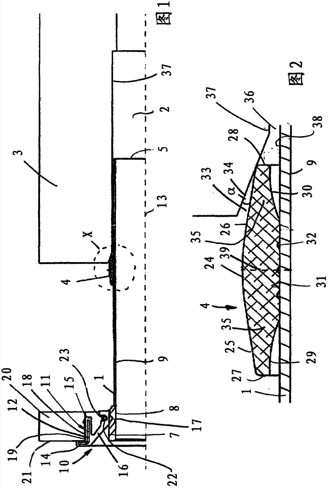
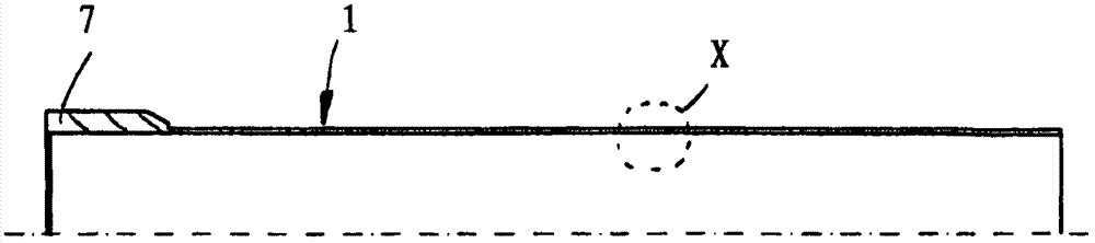
[0027] Combustion chamber seals are used in internal combustion engines of vehicles, in particular motor vehicles. The combustion chamber seal has an injector sleeve 1 which is inserted with one end into a combustion chamber 2 of a cylinder head 3 . The elastically deformable sealing ring 4 in the mounted position serves to seal the injector sleeve 1 in the combustion chamber 2 . The injector sleeve 1 is made, for example, of high-grade steel, preferably stainless steel, but can also be made of other suitable materials, such as ceramic materials, other metallic materials or the like.

[0028] The outer diameter of the injector sleeve 1 is slightly smaller than the diameter of the combustion chamber 2 . The narrow annular gap thus formed is sealed by the elastically deformable sealing ring 4 in the installed position.

[0029] At the end of the injector sleeve 1 protruding from the combustion chamber 2 there is a reinforcing ring 7 whose cylindrical inner side 8 forms a conti...


PUM


Abstract

A combustion chamber gasket seal for internal combustion engines of vehicles, preferably of motor vehicles, comprising an injector sleeve which projects into a combustion chamber of a cylinder head and carries at least one elastomer sealing ring that seals the combustion chamber relative to the exterior, comprises a sealing ring which is arranged detachably on the injector sleeve and is seated on the injector sleeve with elastic deformation at least with force fit.

Description

technical field [0001] The invention relates to a combustion chamber seal for an internal combustion engine of a vehicle, in particular a motor vehicle, according to the preamble of claim 1 . Background technique [0002] For sealing the combustion chamber, the injector sleeve, into which the injector sleeve is inserted, has a sealing ring which is vulcanized on the outside of the injector sleeve. The sealing ring is provided on the outside with sealing ribs which are elastically deformable in the installed position. Usually after several fittings and dismountings of the injector sleeve, the sealing ring wears down so much that it has to be replaced. However, since the sealing ring is vulcanized onto the injector sleeve, the injector sleeve must also be replaced. [0003] Producing the injector sleeve from vulcanized sealing rings is also complicated and cost-intensive. Pretreatment of the injector sleeve is required for the vulcanization process, especially if the inject...

Claims


Application Information

Patent Timeline
Patent Type & Authority Applications(China)
IPC IPC(8): F02F11/00F16J15/06
CPCF02F11/002F16J15/106
Inventor F·彼尔戈M·卡斯尼-切里希M·特勒
Owner KACO WUXI
Why Eureka
Try Eureka