Cylinder base of pneumatic motor

A technology of air motors and cylinder seats, applied in fluid pressure actuating devices, mechanical equipment, etc., can solve the problems of air seat positioning, air seat offset, etc., achieve good positioning and avoid offset effects

Inactive Publication Date: 2015-06-24
付菁
View PDF0 Cites 0 Cited by
  • Summary
  • Abstract
  • Description
  • Claims
  • Application Information

AI Technical Summary

Problems solved by technology

When assembling this kind of traditional cylinder seat, it is necessary to install the air seat at the air inlet and the air outl

Method used


Image

  • Cylinder base of pneumatic motor
  • Cylinder base of pneumatic motor

Examples


Embodiment Construction

[0010] The preferred embodiments of the present invention will be described in detail below in conjunction with the accompanying drawings.

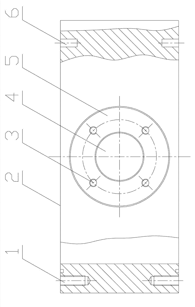
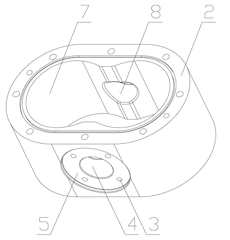
[0011] see figure 1 and figure 2 , the present invention has a cylinder body 2, the cylinder body 2 is provided with an inner cavity 7, the side wall of the cylinder body 2 is provided with an air inlet 4 and an air outlet 8 arranged oppositely, and the top of the cylinder body 2 is provided with a bolt hole 1 and pin holes 6; in particular: the air inlet 4 and the air outlet 8 are located on the cylinder body 2 and also have a positioning groove 5 for positioning the air seat, and there are four positioning grooves located on the cylinder body 2 in the positioning groove 5 There are two screw holes 3 evenly distributed in a circle.


PUM


Abstract

The invention discloses a cylinder base of a pneumatic motor. The cylinder base comprises a cylinder provided with an inner cavity; the side walls of the cylinder are provided with an air inlet and an air outlet which are formed oppositely; the top of the cylinder is provided with bolt holes and pin holes. The cylinder base is characterized in that the air inlet and air outlet of the cylinder are provided with positioning grooves used for positioning an air connecting base, and a plurality of screw holes are formed in the positioning grooves of the interior of the cylinder. The cylinder base is provided with the positioning grooves, so that the air connecting base can be positioned well and can be prevented from shifting.

Description

technical field [0001] The invention relates to the technical field of air motors, in particular to a cylinder seat of an air motor. Background technique [0002] The cylinder seat of the traditional air motor has a cylinder body, the cylinder body is provided with an inner cavity, the side wall of the cylinder body is provided with an air inlet and an air outlet arranged oppositely, and the top of the cylinder body is provided with a bolt hole and a pin hole. When this traditional cylinder block is assembled, it is necessary to install air receiving seats at the air inlet and air outlet. Since the air inlet and air outlet cannot be positioned against the air connecting seats, the air receiving seats often deviate. Therefore, it is very necessary to design a cylinder block that can well solve the above problems. Contents of the invention [0003] The object of the present invention is to improve the above-mentioned deficiencies in the prior art, and provide a cylinder sea...

Claims


Application Information

Patent Timeline
IPC IPC(8): F15B15/20
CPCF15B15/20F15B2215/30
Inventor 付菁
Owner 付菁
Why Eureka
Try Eureka