

Control method, electronic devices and system
A technology of electronic equipment and a control method, which is applied in the electronic field and can solve problems such as single screen content
- Summary
- Abstract
- Description
- Claims
- Application Information
AI Technical Summary
Problems solved by technology
Method used
Image

Examples
Embodiment 1
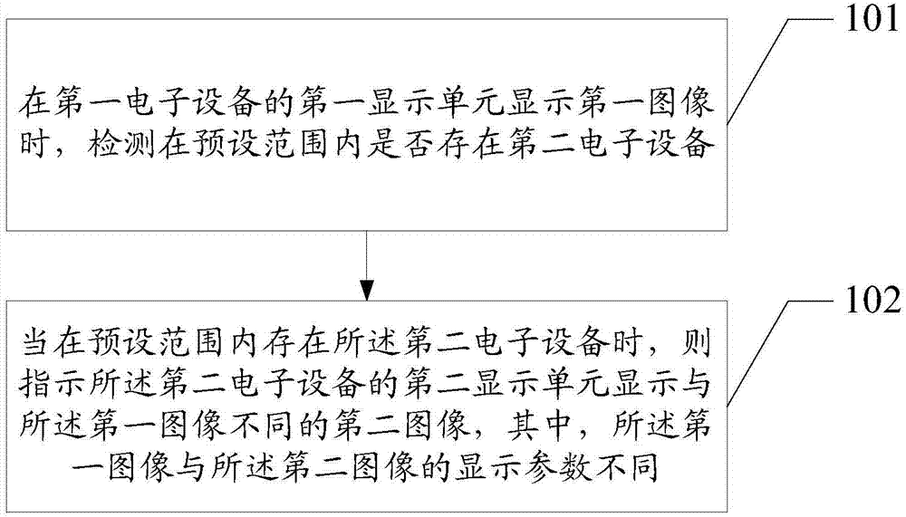
[0077] Please refer to figure 1 , Embodiment 1 of the present application provides a control method, the method comprising:
[0078] Step 101: Detect whether a second electronic device exists within a preset range when a first display unit of the first electronic device displays a first image.
[0079] When the display unit of the first electronic device is playing audio-visual images or displaying images, a detection device, such as a sensor, a locator, a signal tracker, a camera, or other devices that can detect the distance between two objects can be realized etc., to detect whether there is a second electronic device within a preset range, the detection device can be set on the first electronic device, for example, an infrared sensor set on the first electronic device, or can be set on In the preset range, for example, the camera installed in a house, of course, can also be installed in any other place where the spatial position distance between the first electronic devic...
Embodiment 2
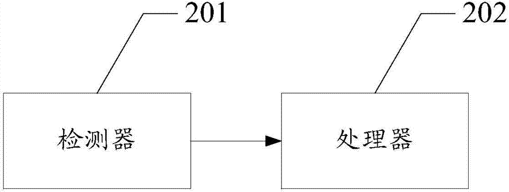
[0131] Please refer to figure 2 , Embodiment 2 of the present application provides an electronic device, including:
[0132] A detector 201, configured to detect whether an electronic device exists within a preset range;
[0133] The processor 202 is configured to control the detector to detect whether the electronic device exists within a preset range when the first display unit of the electronic device displays a first image; When using the electronic device, instruct the second display unit of the electronic device to display a second image different from the first image, wherein the display parameters of the first image and the second image are different.
[0134] Specifically, the first image is specifically:
[0135] An image taken from a first angle in the first scene;
[0136] The second image is specifically:
[0137] An image taken from a second angle different from the first angle under the first scene.
[0138] Specifically, the processor is further configure...
Embodiment 3
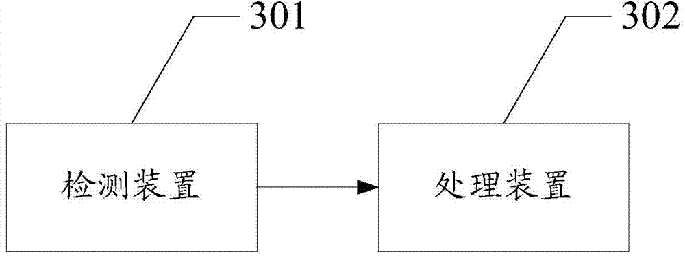
[0146] Please refer to image 3 , Embodiment 3 of the present application provides a system, the system includes:
[0147] A detecting device 301, configured to detect whether a second electronic device exists within a preset range of the first electronic device when the first display unit of the first electronic device displays the first image;
[0148] The processing device 302 is configured to, when the second electronic device exists within the preset range of the first electronic device, instruct the second display unit of the second electronic device to display an image different from that of the first image. The second image, wherein the display parameters of the first image and the second image are different.
[0149] Specifically, the first image is specifically:
[0150] An image taken from a first angle in the first scene;
[0151] The second image is specifically:
[0152] An image taken from a second angle different from the first angle under the first scene. ...
PUM
 Abstract
Description
Claims
Application Information