Large building solar photovoltaic power generation device

A technology of solar photovoltaic and power generation devices, applied in the field of solar power generation, can solve the problems of high cost, high price, and inability to improve enthusiasm, etc., and achieve the effect of improving power generation utilization and increasing investment enthusiasm

Inactive Publication Date: 2015-06-24
CHINA IPPR INT ENG
View PDF6 Cites 3 Cited by
  • Summary
  • Abstract
  • Description
  • Claims
  • Application Information

AI Technical Summary

Problems solved by technology

In the existing solar power generation system, it is mainly to set up solar photovoltaic power generation equipment or solar power generation houses at specific locations with sufficient solar energy. However, if green solar energy technology is to be extended to the majority of users, it is necessary to apply solar photovoltaic power generation devices to In large buildings, and adaptive transformation is carried out, the existing mature household solar power generation system is connected to the battery through the solar photovoltaic array, and the converted electric energy is stored through the battery, and the electric energy in the battery is directly used to realize the utilization of solar energy when in use. However, this home solar power generation system is only suitable for small and medium-scale use of a single family. If each family is equipped with a set of equipment, not only the price is high, but also the cost is high, and the solar photovoltaic power generation that is uniformly used in large civil buildings has not been realized. device
[0003] Through searching, the inventor has also found that although there are currently some systems that feed the electric energy generated by solar photovoltaic power generation devices placed in large buildings into the grid, on the one hand, this cannot increase the owner's own investment in solar photovoltaic power generation devices. On the other hand, if all the generated energy is directly fed into the grid, it will also reduce the power generation efficiency of solar photovoltaic power generation devices

Method used


Image

  • Large building solar photovoltaic power generation device

Examples


Embodiment Construction

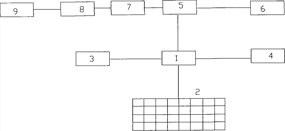
[0008] The schematic diagram of the large-scale building solar photovoltaic power generation device of the present invention is as follows figure 1 shown. The solar photovoltaic power generation device of the present invention is usually arranged on the top roof of a large building, or is erected on the outer façade at the top of the building. The solar photovoltaic power generation device mainly includes a control circuit 1 , a solar photovoltaic array 2 , a solar photovoltaic battery pack 3 , a DC output terminal 4 , an AC output terminal 6 , an inverter 5 , an electric energy meter 7 , and a high / low voltage transformer 8 .

[0009] As mentioned above, the photovoltaic array is usually installed on the roof of a large building, and the solar photovoltaic array is electrically connected with the solar photovoltaic battery pack, so that the solar photovoltaic array converts the solar energy into electrical energy and feeds the solar photovoltaic battery pack. The control cir...


PUM


Abstract

The invention designs a large building solar photovoltaic power generation device and method. The device comprises a control circuit, a solar photovoltaic array, a solar photovoltaic cell pack, a direct-current output end, an alternating-current output end, an inverter, an electric energy counter and a transformer. The solar photovoltaic array is connected with the solar photovoltaic cell pack. The control circuit is connected with the solar photovoltaic array, the solar photovoltaic cell pack, the direct-current output end, the alternating-current output end and the inverter. The inverter is connected to the transformer through the electric energy counter. By means of the large building solar photovoltaic power generation device, on one hand, the power generation utilization rate of the solar photovoltaic power generation device is fully improved, and the effects of on-site power generation and on-site usage are achieved; on the other hand, the input enthusiasm of owners of a building to the solar photovoltaic power generation device is also improved.

Description

technical field [0001] The invention relates to the field of solar power generation, and more particularly to a solar photovoltaic power generation device for large buildings. Background technique [0002] With the continuous deepening of the concept of green energy into the hearts of the people, people are paying more and more attention to environmentally friendly green energy. Among the existing energy sources, solar energy is a clean and reusable energy source. In the existing solar power generation system, solar photovoltaic power generation equipment or solar power generation houses are mainly installed in specific locations with sufficient solar energy. To promote green solar energy technology to a large number of users, it is necessary to apply solar photovoltaic power generation devices to In large buildings, and adapt to the transformation, the existing mature household solar power generation system is connected to the battery through the solar photovoltaic array, ...

Claims


Application Information

Patent Timeline
Patent Type & Authority Applications(China)
IPC IPC(8): H02S40/38H02J3/38
CPCH02S40/00Y02B10/10Y02E10/50Y02E70/30
Inventor 邢岷峰才振刚史大鸣俞健涵朱江
Owner CHINA IPPR INT ENG
Why Eureka
Try Eureka