Attachment structure for vehicle device

A technology for vehicles and equipment, applied in the field of installation structure of equipment for vehicles, can solve the problems of wrong inverter and auxiliary battery disassembly, etc., and achieve the effect of reliable disassembly

Inactive Publication Date: 2015-06-24
NISSAN MOTOR CO LTD
View PDF5 Cites 3 Cited by
  • Summary
  • Abstract
  • Description
  • Claims
  • Application Information

AI Technical Summary

Problems solved by technology

[0009] However, in the conventional technology described above, both the inverter and the auxiliary battery are constructed so that they can be removed before other devices, so there is a possibility that the inverter and the auxiliary battery may be removed in the wrong order.

Method used


Image

  • Attachment structure for vehicle device
  • Attachment structure for vehicle device
  • Attachment structure for vehicle device

Examples


Embodiment Construction

[0032] below, with Figure 1 Embodiments of the present invention will be described in detail.

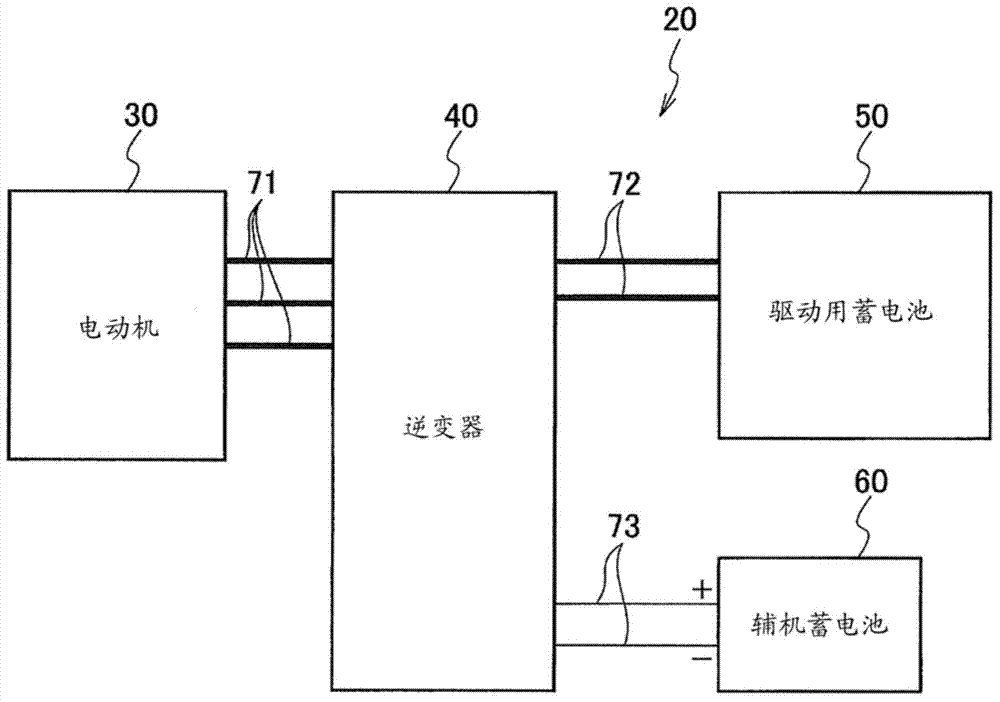
[0033] A motor drive system 20 having an electric motor 30 is mounted on the vehicle 10 of the present embodiment (see figure 1 ). That is, the vehicle 10 utilizes the electric motor 30 as a power source. Such vehicles include, for example, an electric vehicle driven by the driving force of an electric motor, a hybrid vehicle combining an internal combustion engine and an electric motor, and a fuel cell vehicle driven by electric power generated by a fuel cell.

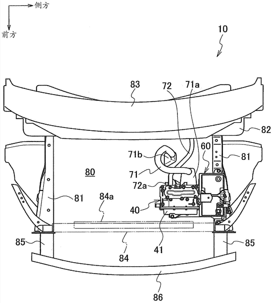
[0034] Such as figure 1 As shown, the motor drive system 20 includes a motor 30 that is connected to a driving wheel (not shown) and transmits power to the driving wheel. The inverter 40 is electrically connected to the motor 30 through a first harness 71 , and the driving battery (power supply unit) 50 is electrically connected to the inverter 40 through a second harness 72 . In addition, if figure 2 As shown, at b...


PUM


Abstract

An attachment structure for a vehicle device, wherein an inverter attachment unit (150) having an inverter (40) is attached to a vehicle body (130). An auxiliary battery attachment unit (160) having an auxiliary battery (60) is also attached to the vehicle body (130) so as to be adjacent to the inverter attachment unit (150). When the auxiliary battery attachment unit (160) is attached to the vehicle body (130), sections (181a, 181b) where the inverter attachment unit (150) and the vehicle body (130) are attached are covered by the auxiliary battery attachment unit (160).

Description

technical field [0001] The present invention relates to a mounting structure of vehicle equipment. Background technique [0002] Conventionally, as a mounting structure for vehicle equipment, there is known a mounting structure for mounting vehicle equipment such as an inverter and an auxiliary battery (auxiliary battery) to a vehicle body (for example, refer to Patent Document 1). [0003] In this Patent Document 1, the auxiliary battery and the inverter are attached to the vehicle body in a state of being adjacent to each other. [0004] prior art literature [0005] patent documents [0006] Patent Document 1: (Japanese) Unexamined Patent Application Publication No. 2012-166653 [0007] The problem to be solved by the invention [0008] However, the inverter and the auxiliary battery are usually removed from the vehicle body in a predetermined order. [0009] However, in the conventional technology described above, both the inverter and the auxiliary battery have a s...

Claims


Application Information

Patent Timeline
Patent Type & Authority Applications(China)
IPC IPC(8): B60K1/00B60R16/04B60L50/16
CPCB60K1/00B60R16/04B60Y2304/01B60L2210/40B60L2270/145Y02T10/70B60L50/16B60L50/51B60L58/20B60L50/66B60L50/64B60L58/40Y10S903/951B60L15/007B60K1/04Y02T10/64Y02T10/7072Y02T10/72Y02T90/40B60K2001/0411
Inventor 小林裕
Owner NISSAN MOTOR CO LTD
Why Eureka
Try Eureka