
Vehicle wheel

A technology of wheels and spokes, which is applied in the field of fastening and connection components of wheels, can solve the problems of no use value, difficulty in locking the rotation sleeve, and inability to take it out from the first rotation stopping hole, etc., and achieve a good locking effect

Pending Publication Date: 2016-12-14
杨东佐
View PDF9 Cites 2 Cited by
  • Summary
  • Abstract
  • Description
  • Claims
  • Application Information

AI Technical Summary

Problems solved by technology

[0013] Aiming at the problems existing in the prior art, the technical problem to be solved by the present invention is to overcome the existing anti-loosening technology that those skilled in the art believe that the anti-loosening sleeve is used to restrict the rotation of the nut relative to the screw to realize the reverse loosening of the bolt and nut. Solution, because the anti-rotation sleeve is difficult or impossible to take out from the first anti-rotation hole, resulting in inertial thinking of no use value, the present invention provides a wheel, which uses a anti-rotation sleeve to limit the relative rotation of the threaded pair, so that the threaded pair cannot It will be loosened due to reverse rotation and the anti-rotation sleeve can be taken out from the first anti-rotation hole quickly, conveniently and reliably, so that the detachment of the screw, nut, etc. is fast, convenient and reliable.

Method used


Image

  • Vehicle wheel
  • Vehicle wheel
  • Vehicle wheel

Examples


Embodiment 1

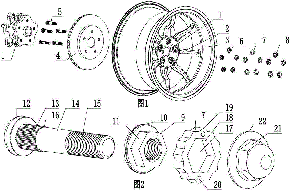
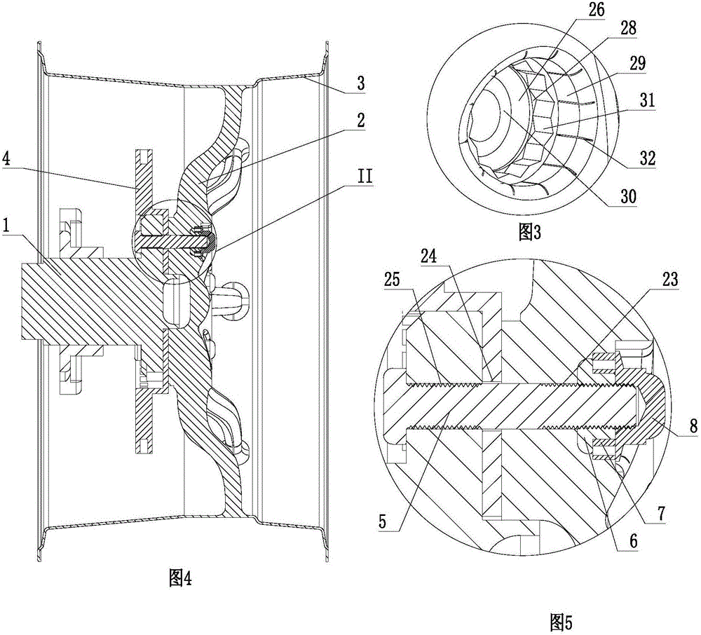
[0105] Such as Figure 1 to Figure 5 As shown, a wheel includes a hub 1, a spoke 2, a rim 3, a brake 4, and multiple sets of fastening and connecting components.

[0106] The fastening connection assembly includes a screw rod 5, a lock nut 6, an anti-rotation sleeve 7, and a stopper for the anti-rotation sleeve. The stopper of the anti-rotation sleeve is a blocking nut 8.

[0107] The lock nut 6 includes a regular hexagonal anti-rotation portion 9 , a cylindrical abutting portion 10 protruding radially from the anti-rotation portion 9 , and an end surface of the cylindrical abutment portion 10 transitions with a circular arc on the side. The six anti-rotation planes on the outer periphery of the anti-rotation portion 9 form six first anti-rotation portions 11 arranged in the circumferential direction. A threaded through hole is provided at the axial center of the lock nut 6 .

[0108] The screw rod 5 includes a resisting portion 12, an anti-rotation shaft 13, a polished rod...

Embodiment 2

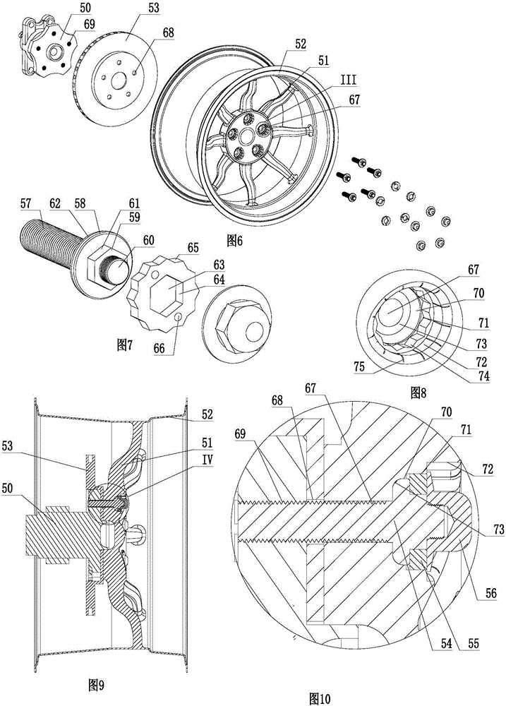
[0115] Such as Figure 6 to Figure 10 As shown, a wheel includes a hub 50, a spoke 51, a rim 52, a brake 53, and multiple sets of fastening and connecting components.

[0116] The fastening connection assembly includes a screw rod 54, an anti-rotation sleeve 55, and a stopper for the anti-rotation sleeve. The stopper of the anti-rotation sleeve is a resisting nut 56 .

[0117] The screw 54 includes a first external thread portion 57 , a cylindrical resisting portion 58 , a regular hexagonal anti-rotation portion 59 , and a second external thread portion 60 arranged in sequence. The resisting portion 58 protrudes radially from the first external thread portion 57 and the anti-rotation portion 59 , and the anti-rotation portion 59 radially protrudes from the second external thread portion 60 . The six anti-rotation planes on the outer periphery of the anti-rotation portion 59 form six first anti-rotation portions 61 arranged in the circumferential direction. The outer periphe...

Embodiment 3

[0123] Such as Figure 11 to Figure 15 As shown, the difference from Embodiment 2 is that two removal grooves 92 communicating with the first rotation prevention hole 91 are also provided on the wall of the resisting nut accommodation hole 90 and the first rotation prevention hole 91, and the removal grooves 92 It is flush with the bottom surface of the first anti-rotation hole 91 . The anti-rotation sleeve 93 is provided with a guide inclined surface 94, and the guide inclined surface 94 faces the bottom surface of the first anti-rotation hole 91. Space 96.

[0124] The disassembly method of the wheel includes the following steps:

[0125] First, the blocking nut 97 is separated from the second external thread portion 99 of the screw rod 98;

[0126] Then use the pliers 100 to take out the anti-rotation sleeve 93 from the first anti-rotation hole 91 : the pliers 100 includes a left pliers body 101 and a right pliers body 102 that are rotatably pivoted together. The left p...


PUM


Abstract

The invention discloses a vehicle wheel which comprises a hub, a spoke, a braking element and fastening connection components, wherein each fastening connection component is composed of a screw rod and a rotation retaining sleeve; the screw rods fix the hub, the spoke and the braking element together; the spoke is provided with first rotation retaining holes; a fetching structure used for fetching each rotation retaining sleeve which is installed out of a locking nut and in the corresponding first rotation retaining hole is arranged on the wall of each first rotation retaining hole and / or each rotation retaining sleeve; each rotation retaining sleeve is installed out of a rotation retaining holding part of the corresponding screw rod and in the corresponding first rotation retaining hole; a third rotation retaining part of a first rotation retaining through hole of each rotation retaining sleeve is matched with a fourth rotation retaining part arranged outsides the corresponding rotation retaining holding part to restrain rotation of the corresponding screw rod relative to a corresponding first rotation retaining sleeve; a second rotation retaining part arranged at the periphery of each rotation retaining sleeve is matched with a first rotation retaining part of the corresponding first rotation retaining hole to restrain rotation of the corresponding first rotation retaining sleeve relative to spoke; and the screw rods and the spoke are installed together without capability of rotation. The vehicle wheel has the advantages that a threaded connection pair cannot get loose due to reversed rotation, so that threaded connection is kept at a locking position which is initially needed and is reliable, and fetching of the rotation retaining sleeves is convenient and reliable.

Description

Technical field: [0001] The invention relates to a wheel; in particular, it relates to a fastening connection assembly of the wheel. Background technique [0002] The thread pair mechanical static connection between objects often encounters safety problems and safety accidents caused by the breakage of the bolts connected to some key parts and the failure of the threaded connection. It is a common problem faced by the world, and it is also an urgent need for continuous research and improvement by technicians in this field. Solve problems that have not been solved. Small bolts, big accidents, major accidents often occur due to bolt breakage, such as cylinder smashing accidents caused by breakage of connecting rod bolts of automobile engines; on April 18, 2009, 1 death and 4 injuries were caused by the breakage of Harbin tower crane bolts; according to China Taiwan media reported that the No. 1 reactor of the No. 2 Nuclear Power Plant detected seven anchor bolts that were bro...

Claims


Application Information

Patent Timeline
IPC IPC(8): F16B39/282B60B27/06
CPCB60B27/065F16B39/282F16B39/28
Inventor 杨东佐
Owner 杨东佐
Learn More