Carving tool bit of carving machine

A technology of engraving knives and engraving machines, which is applied in the field of engraving knife heads, can solve problems such as low production efficiency, time-consuming and laborious, and extensive control methods, and achieve the effect of accurate engraving, precision assurance, and high efficiency

Active Publication Date: 2015-07-01
HEFEI AORUI DIGITAL CONTROL SCI & TECH
View PDF6 Cites 4 Cited by
  • Summary
  • Abstract
  • Description
  • Claims
  • Application Information

AI Technical Summary

Problems solved by technology

In the prior art, the depth of engraving is generally controlled by controlling the power output of the engraving head, but this control method is too extensive and needs to rely entirely on the mechanical control ability of the operator, which requires extremely high ability of the operator. Time-consuming and labor-intensive, low production efficiency

Method used


Image

  • Carving tool bit of carving machine
  • Carving tool bit of carving machine
  • Carving tool bit of carving machine

Examples


Embodiment 1

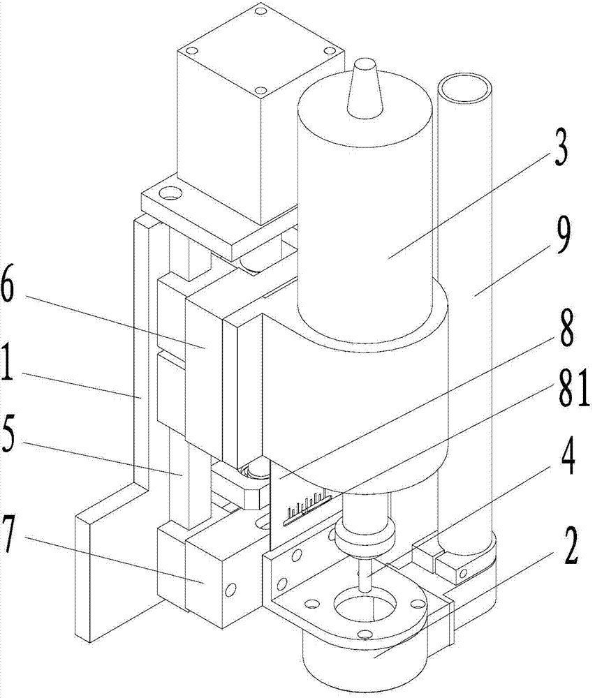
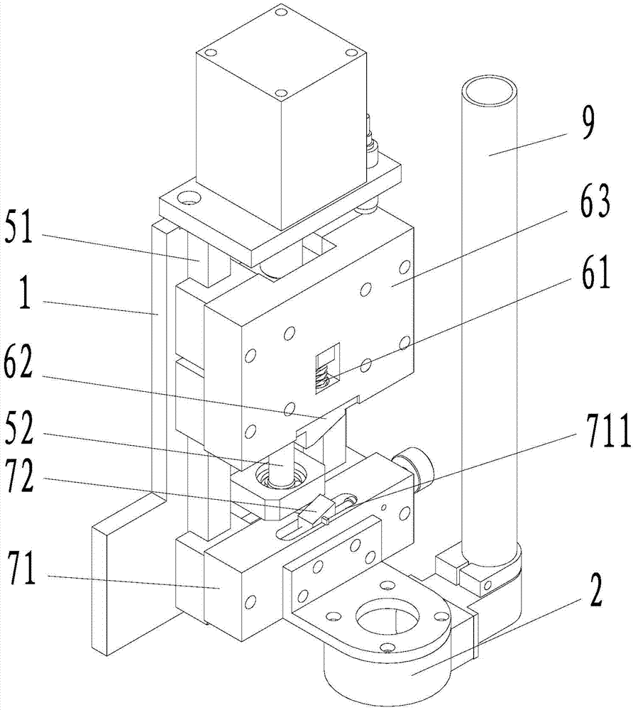
[0022] A kind of engraving head of engraving machine of the present embodiment has such as Figure 1~3 The shown structure comprises a fixed plate 1, a limiting disc 2, a tool seat 3, and a milling cutter 4 arranged on the tool seat 3. The limiting disc 2 is provided with a through hole for the milling cutter 4 to pass through. It includes a longitudinal guide rail 5 arranged on the fixed plate 1, an upper linear motion mechanism 6 and a lower linear motion mechanism 7 arranged on the longitudinal guide rail 5, the upper linear motion mechanism 6 is fixedly connected with the tool holder 3, and the lower linear motion mechanism The mechanism 7 is fixedly connected with the limit plate 2, wherein:

[0023] The longitudinal guide rail 5 includes a longitudinal sliding guide rail 51 and a longitudinal driving guide rail 52 parallel to each other, and a driving block 53 is arranged on the longitudinal driving guide rail 52;

[0024] The upper linear motion mechanism 6 includes a ...
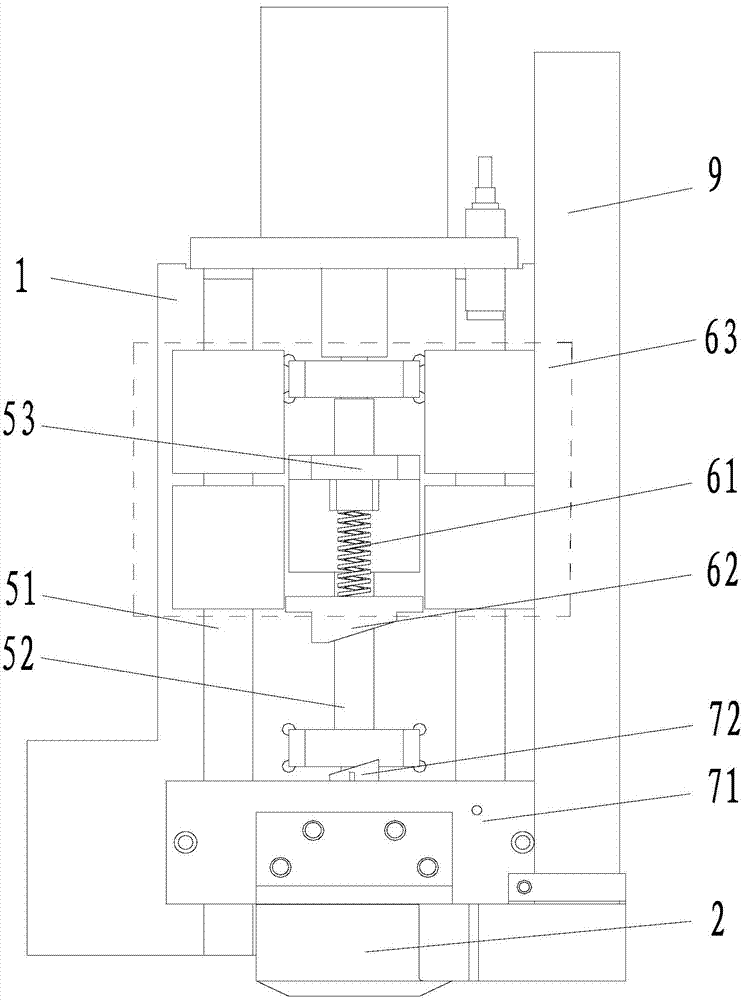
Embodiment 2

[0033] A kind of engraving head of engraving machine of the present embodiment has such as Figure 4 In the above structure, a base 11 extends forward from the bottom end of the fixed plate 1, and the lower linear motion mechanism 7 also includes a longitudinally telescopic lower spring, and the lower end of the lower spring is fixed on the base 11, Its upper end is fixedly connected with the lower surface of the lower connector 71, but the connection mode between the upper end of the lower spring and the lower surface of the lower connector 71 is not limited to this, for example, the two are in contact with each other, but not fixedly connected, etc., also belong to the present invention Protection range; the compression spring force value of the upper spring is greater than the compression spring force value of the lower spring; the function of the lower spring is to provide double buffer protection for the fitting of the limit plate 2, so as to ensure that the limit plate 2 ...


PUM


Abstract

The invention discloses a carving tool bit of a carving machine. The carving tool bit comprises a fixing plate (1), a limiting plate (2), a tool apron (3) and a milling cutter (4), and further comprises a longitudinal guide rail (5) on the fixing plate (1), an upper linear moving mechanism (6) on the longitudinal guide rail (5) and a lower linear moving mechanism (7), the upper linear moving mechanism (6) is fixedly connected with the tool apron (3), and the lower linear moving mechanism (7) is fixedly connected with the limiting plate (2). By means of the carving tool bit, carving depth can be precisely set according to needs, the carving depth can be kept consistent all the time, and carving precision is guaranteed. Compared with the prior art, the carving tool bit of the template carving machine does not depend on mechanical maneuvering ability of operators, carving is precise, and efficiency is high.

Description

technical field [0001] The invention relates to an automatic engraving device, in particular to an engraving cutter head of an engraving machine. Background technique [0002] At present, engraving machines are widely used in various fields. According to different engraving methods, engraving machines can be divided into laser engraving machines and mechanical engraving machines, among which mechanical engraving machines have the widest application range. In the technical field of automatic engraving, the engraving head of the engraving machine is the core of the entire equipment, and the precision of the engraving head directly determines the fineness of engraving. In the prior art, the depth of engraving is generally controlled by controlling the power output of the engraving head, but this control method is too extensive and needs to completely rely on the mechanical control ability of the operator, which requires extremely high ability of the operator. Time-consuming an...

Claims


Application Information

Patent Timeline
IPC IPC(8): B44B3/00B44B3/06
Inventor 罗华
Owner HEFEI AORUI DIGITAL CONTROL SCI & TECH
Why Eureka
Try Eureka