Magnetic latching relay with dual-holder magnetic circuit structure and assembly method of magnetic latching relay
A technology of magnetic latching relays and assembly methods, which is applied in the direction of electromagnetic relays, electromagnetic relay details, relays, etc., can solve the problems of increasing relay non-conduction, increasing the difficulty of assembly, and affecting the efficiency of assembly, so as to reduce difficulty and avoid Assembly dross, effect of reducing accumulated tolerances
- Summary
- Abstract
- Description
- Claims
- Application Information
AI Technical Summary
Problems solved by technology
Method used
Image
Examples
Embodiment 1
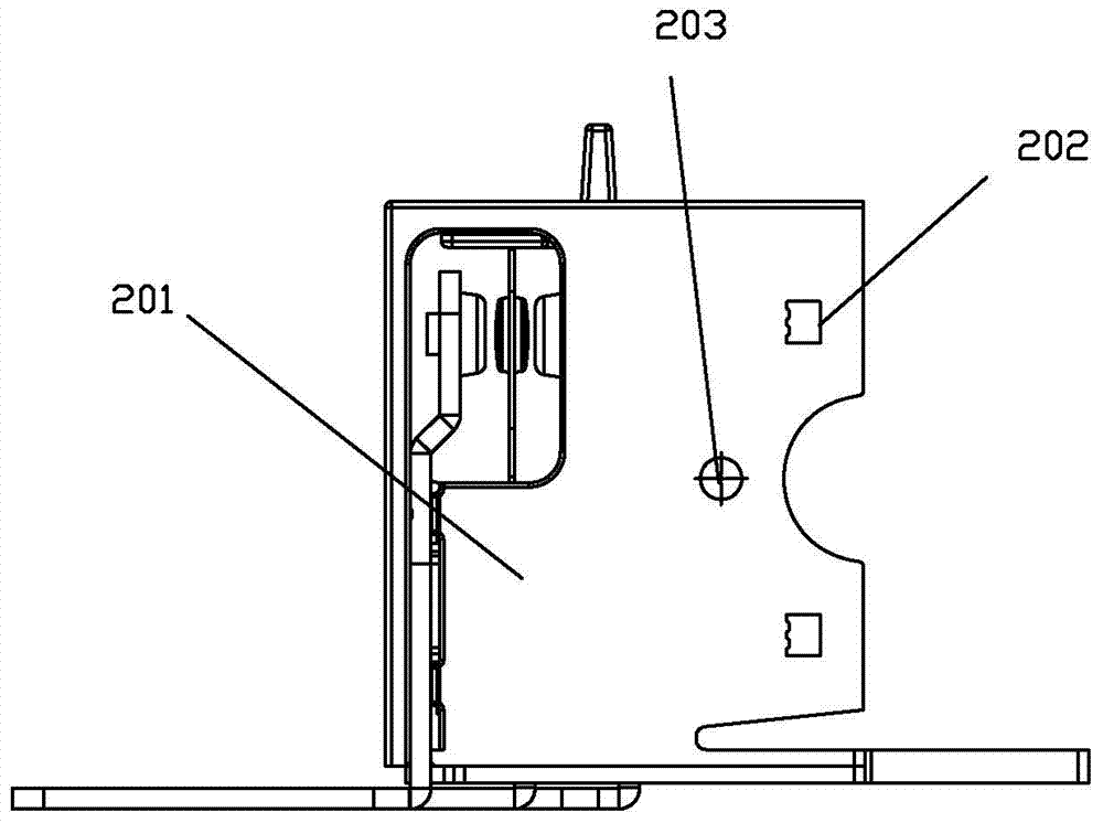
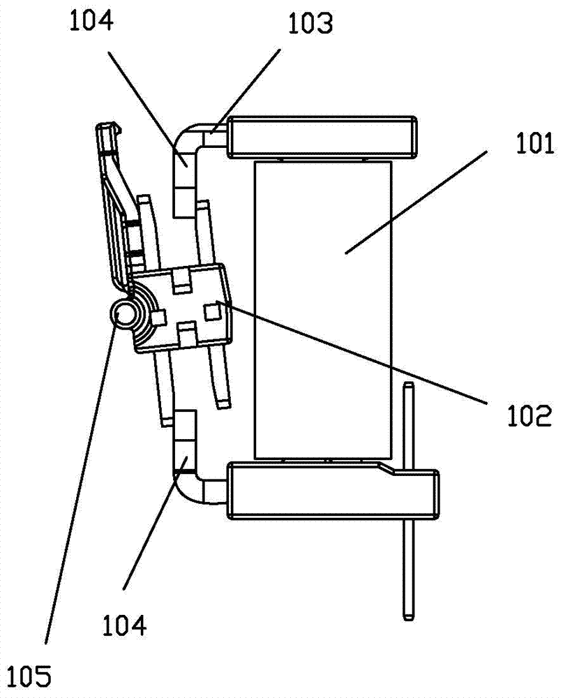
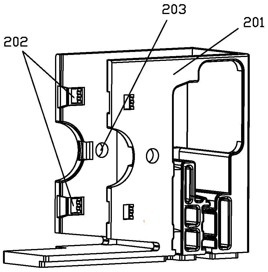
[0071] see Figure 5 to Figure 18 As shown, a magnetic latching relay with a double fixed frame magnetic circuit structure of the present invention includes a magnetic circuit part 1, an armature part 2 and a base 3; the magnetic circuit part 1 has a yoke 11, and the yoke 11 has two One is the upper and lower yokes, the two sides of the yoke 11 have a first boss 111, and the armature part 2 has a rotating shaft 21; it also includes a fixing frame 4, and the fixing frame 4 is provided with a first boss for matching with the magnetic circuit part. The fixing hole 41 of the table 111 and the rotating shaft hole 42 used to match the rotating shaft 21 of the armature part; the fixed frame 4 is two, respectively matched on both sides of the magnetic circuit part and the armature part to form a magnetic circuit system of an overall shape An assembly; an insertion structure is provided between the inner side of the two side walls 31 of the base and the corresponding fixing frame, and ...
Embodiment 2
[0094] see Figure 19 to Figure 26 As shown, a magnetic latching relay with a double fixed frame magnetic circuit structure of the present invention differs from the first embodiment in that the insertion structure is different. The insertion structure of this embodiment is arranged on the side wall of the base The inner side is the second vertical guide groove 33 and the outer surface of the fixed frame is the second vertical boss 46, and the second boss 46 of the fixed frame is vertically fitted on the base In the second guide groove 33.
[0095] Another difference is that the fixing hole 41 of the fixing frame used to fit the first boss 111 of the magnetic circuit part and the shaft hole 42 used to fit the shaft 21 of the armature part are both blind holes.
Embodiment 3
[0097] see Figure 27 to Figure 33 As shown, a magnetic latching relay with a double fixed frame magnetic circuit structure of the present invention differs from the first embodiment in that the insertion structure is different. The insertion structure of this embodiment is arranged on the side wall of the base The inner side is the third vertical boss 34 and the outer surface of the fixed frame is the third vertical guide groove 47, and the third guide groove 47 of the fixed frame is vertically fitted on the base In the third boss 34 of.
PUM
 Abstract
Description
Claims
Application Information
 - R&D
- Intellectual Property
- Life Sciences
- Materials
- Tech Scout
- Unparalleled Data Quality
- Higher Quality Content
- 60% Fewer Hallucinations
Browse by: Latest US Patents, China's latest patents, Technical Efficacy Thesaurus, Application Domain, Technology Topic, Popular Technical Reports.
© 2025 PatSnap. All rights reserved.Legal|Privacy policy|Modern Slavery Act Transparency Statement|Sitemap|About US| Contact US: help@patsnap.com


