

Method and device for distributing resource blocks in long term evolution system
A technology for long-term evolution system and resource allocation, applied in the field of resource block allocation, which can solve problems such as resource interference, reduce the probability of mutual interference between resources and improve performance.
- Summary
- Abstract
- Description
- Claims
- Application Information
AI Technical Summary
Problems solved by technology
Method used
Image

Examples
Embodiment 1
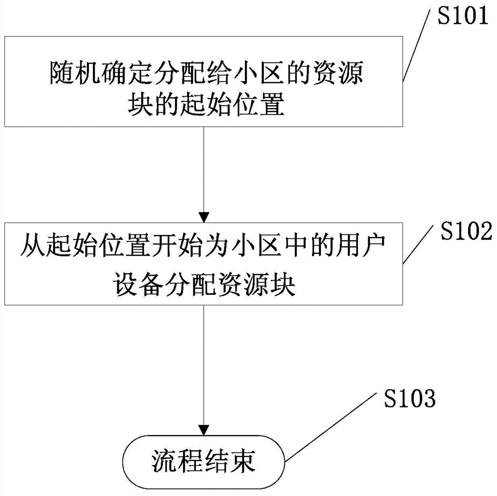
[0025] This embodiment provides a method for allocating resource blocks in a long term evolution system, please refer to figure 1 , figure 1 The schematic flow chart of the method provided in this embodiment specifically includes the following steps:
[0026] Step S101: Randomly determine the starting position of the resource block allocated to the cell.
[0027] In this embodiment, the resource block at the starting position is called the starting resource block.
[0028] In this embodiment, the system randomly assigns a resource block start position to each cell, instead of randomly determining a resource block start position as the resource block start position of each cell.
[0029] In this embodiment, the following method can be used to randomly determine the starting position of the resource block allocated to the cell:
[0030] (1) Number or set labels for resource blocks in the system according to the order of frequency bands from low to high, randomly generate an i...
Embodiment 2
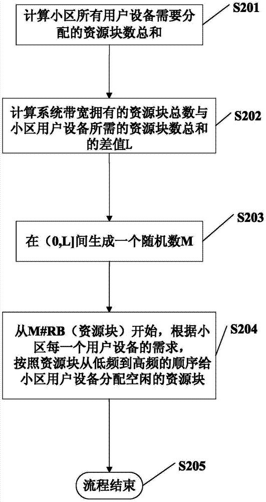
[0040] In order to describe the method provided by the present invention in more detail, this embodiment provides a method for allocating resource blocks in a long term evolution system, please refer to figure 2 , figure 2 It is a flow chart of the method provided in this embodiment.
[0041] Step S201: the cell calculates the sum of the number of RBs required by all scheduling UEs (User Equipment user equipment) in the cell;
[0042] Step S202: The cell calculates the difference between the total number of RBs owned by the system bandwidth and the sum of the number of RBs of UEs in the cell, and the difference is defined as L;
[0043] Step S203: Randomly generate an integer between (0, L], that is, greater than zero and less than or equal to L, defined as M;
[0044] Step S204: Use M#RB as the initial resource block allocated to the cell, starting from M#RB, allocate idle time to all UEs to be scheduled in the cell in the order of RBs from low frequency to high frequency a...
Embodiment 3
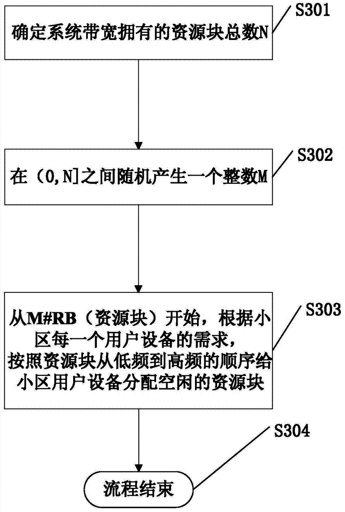
[0047] In order to describe the method provided by the present invention in more detail, this embodiment provides a method for allocating resource blocks in a long term evolution system, please refer to image 3 , image 3 It is a flow chart of the method provided in this embodiment.
[0048] Step S301: Determine the total number N of RBs owned by the system bandwidth;
[0049] Step S302: Randomly generate an integer between (0, N], that is, between greater than zero and less than or equal to N, defined as M;
[0050] Step S303: Use M#RB as the initial resource block allocated to the cell, start from M#RB, allocate idle time to all UEs to be scheduled in the cell in the order of RBs from low frequency to high frequency according to the number of RBs required by each UE in the cell RB, M#RB represents the Mth resource block starting from the lowest frequency in the system bandwidth resource block;
[0051] Step S304: all users are allocated resource blocks according to requi...
PUM
 Abstract
Description
Claims
Application Information