Antenna branching filter

A demultiplexer and antenna technology, applied in impedance networks, electrical components, multi-terminal pair networks, etc., to achieve the effect of improving intermodulation distortion

Inactive Publication Date: 2015-07-01
MURATA MFG CO LTD
View PDF4 Cites 0 Cited by
  • Summary
  • Abstract
  • Description
  • Claims
  • Application Information

AI Technical Summary

Problems solved by technology

In particular, in the configuration of the antenna duplexer 400 disclosed in Patent Document 1, low-frequency components are enclosed between the resonator and the longitudinally coupled resonator filter circuit due to reflection of the signal due to impedance mismatch. structure, so there is a problem of being prone to generate distorted signals based on intermodulation distortion
[0019] In addition, especially when Tx represents the pass band of the transmitting side circuit and Rx represents the pass band of the receiving side circuit, when a Tx signal having a frequency band lower than the pass band of Rx enters the receiving circuit side, there may be Distorted signals due to IMD are generated in the passband Rx of the receiving side circuit or in the vicinity of the passband of the receiving side circuit

Method used


Image

  • Antenna branching filter
  • Antenna branching filter
  • Antenna branching filter

Examples


no. 1 Embodiment approach

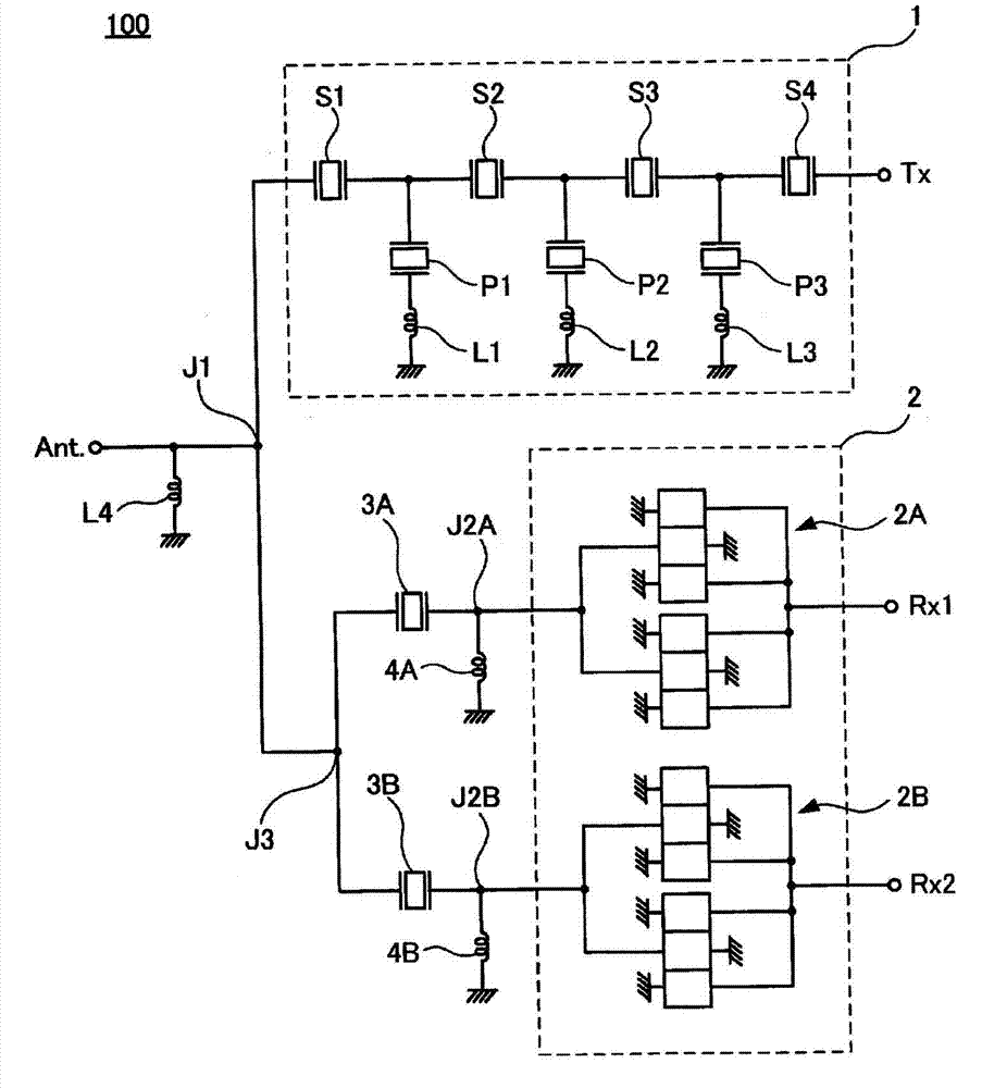
[0041] exist figure 1 An equivalent circuit diagram of the duplexer 100 according to the first embodiment of the present invention is shown.

[0042] The duplexer 100 includes an antenna terminal Ant., a transmission terminal Tx, a first reception terminal Rx1, and a second reception terminal Rx2. In addition, the duplexer 100 includes a first connection point J1, a pair of second connection points J2A, J2B, and a third connection point J3.

[0043]The demultiplexer 100 includes a transmission-side filter circuit 1 having predetermined pass characteristics as a first filter circuit. In this embodiment, the transmission-side filter 1 is a ladder-type SAW filter circuit, and includes: series arm resonators S1, S2, S3, and S4; and a parallel arm connected to the connection point of the series arm resonators S1 and S2. Resonator P1, parallel arm resonator P2 connected at the connection point of series arm resonators S2 and S3, parallel arm resonator P3 connected at the connecti...

no. 2 Embodiment approach

[0070] exist Figure 5 An equivalent circuit diagram of the duplexer 200 according to the second embodiment of the present invention is shown.

[0071] exist figure 1 In the duplexer 100 according to the first embodiment shown, a resonator is constituted by a first resonator 3A and a second resonator 3B, and a first low frequency band pass circuit 4A and a second low frequency band pass circuit 4B A low-frequency band pass circuit is configured, but in the demultiplexer 200 according to the second embodiment, the resonator and the low-frequency band pass circuit are configured separately, and the common resonator 13 and the common low-frequency band pass circuit circuit 14. Furthermore, a common low-frequency band pass circuit 14 is inserted between the connection point J2 located in the middle of the common resonator 13 and the receiving side filter circuit (second filter circuit) 2 , and the ground potential. Other configurations of the demultiplexer 200 are the same as ...

no. 3 Embodiment approach

[0074] exist Figure 6 An equivalent circuit diagram of the duplexer 300 according to the third embodiment of the present invention is shown.

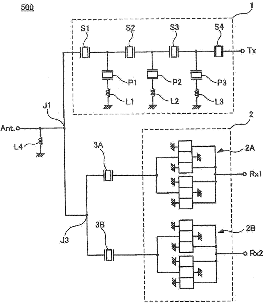
[0075]exist figure 1 In the duplexer 100 according to the first embodiment shown, the inductance element L4 for impedance matching is separately provided, but in the duplexer 300 according to the third embodiment, the inductance element L4 is omitted, and the low frequency band The pass circuits (first low frequency band pass circuit 4A, second low frequency band pass circuit 4B) perform the function of impedance matching. The configuration of the duplexer 300 other than the inductance element L4 is the same as that of the duplexer 100 .

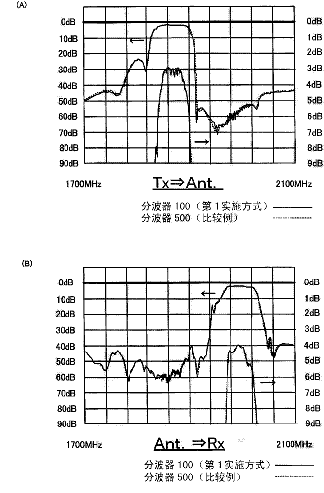
[0076] exist Figure 7 shows the pass characteristics of the demultiplexer 300 according to this embodiment, and figure 2 The transmission characteristics of the duplexer 500 according to the comparative example are shown. as from Figure 7 As known, the pass characteristic of the demultiplex...


PUM


Abstract

Provided is an antenna branching filter having a suppressed intermodulation distortion. The antenna branching filter (100) is provided with: an antenna terminal (Ant.); a first filter circuit (1) having a first pass-band; and a second filter circuit (2) having a second pass-band that does not include the first pass-band and that is a frequency band higher than the first pass-band. The antenna terminal (Ant.), the first filter circuit (1), and the second filter circuit (2) are connected at a first connection point (J1); the second filter circuit (2) is provided with vertically coupled resonator-type filter circuits (2A, 2B); resonators (3A, 3B) are inserted between the first connection point (J1) and the vertically coupled resonator-type filter circuits (2A, 2B); and low-frequency-bandpass circuits (4A, 4B) having a stopband at the second pass-band are inserted between the ground potential and second connection points (J2A, J2B), which are the connection points of the resonators (3A, 3B) and the vertically coupled resonator-type filter circuits (2A, 2B).

Description

technical field [0001] The present invention relates to an antenna duplexer, and more specifically, to an antenna duplexer that suppresses mutual modulation distortion. Background technique [0002] In mobile communication devices such as mobile phones, antenna duplexers (duplexers) are widely used as electronic components for sharing one antenna for both transmission and reception. [0003] exist Figure 9 A conventional antenna duplexer 400 disclosed in Patent Document 1 (JP-A-2005-184143) is shown. [0004] The antenna duplexer 400 includes an antenna terminal 101 . [0005] The antenna terminal 101 is connected to the connection point J. As shown in FIG. [0006] The connection point J is connected to the transmission side filter circuit 102 . The transmission side filter circuit 102 is constituted by a ladder type (SAW) filter circuit. [0007] In addition, the connection point J is connected to the reception-side filter circuit 104 via the resonator 103 . The rece...

Claims


Application Information

Patent Timeline
Patent Type & Authority Applications(China)
IPC IPC(8): H03H9/72H03H7/46H03H9/64
CPCH03H9/6476H03H9/725H03H9/0085H03H9/0009H03H9/706H03H7/38
Inventor 渡边一嗣
Owner MURATA MFG CO LTD
Why Eureka
Try Eureka