3D printing device and method

A 3D printing and liquid storage tank technology, applied in the three-dimensional field, can solve the problems of long optical path of projectors and cannot guarantee the production accuracy, etc., and achieve the effect of short optical path, low graphics deformation rate, and improved molding accuracy.

Inactive Publication Date: 2015-07-08
BOE TECH GRP CO LTD
View PDF9 Cites 28 Cited by
  • Summary
  • Abstract
  • Description
  • Claims
  • Application Information

AI Technical Summary

Problems solved by technology

However, in the actual process, the optical path of the projector is long, and the image will be optically deformed after the light passes through the imaging lens many times, so the production accuracy cannot be guaranteed

Method used


Image

  • 3D printing device and method
  • 3D printing device and method
  • 3D printing device and method

Examples


Embodiment Construction

[0024] In order to make the object, technical solution and advantages of the present invention clearer, the implementation manner of the present invention will be further described in detail below in conjunction with the accompanying drawings.

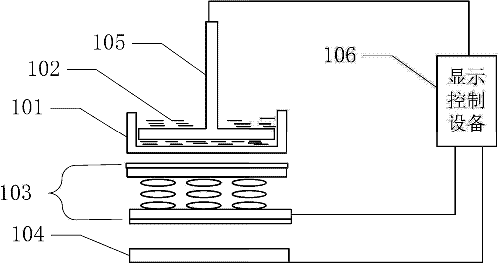
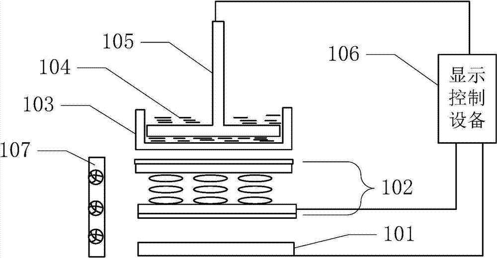
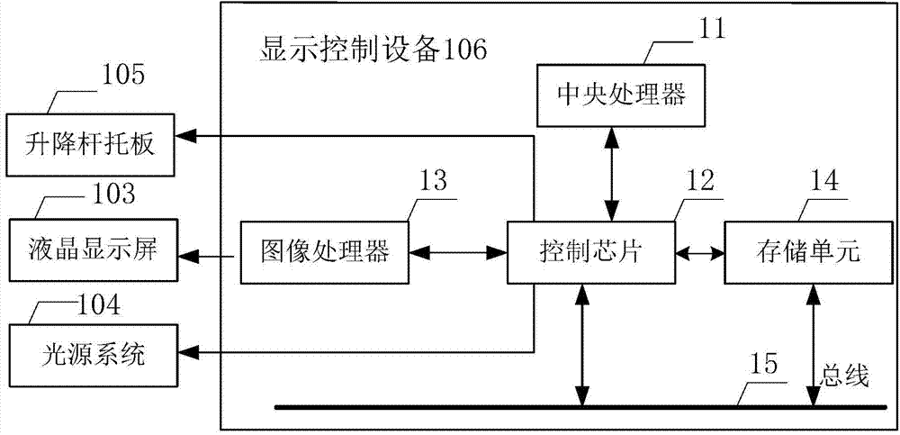
[0025] figure 1 It is a schematic structural diagram of a 3D printing device provided by an embodiment of the present invention. see figure 1 , the device includes: a liquid storage tank 101 with a transparent tank bottom, a liquid crystal display 103, a light source system 104, a lifting rod supporting plate 105 and a display control device 106;

[0026] Wherein, the liquid storage tank 101 with a transparent tank bottom is used to accommodate the liquid photopolymerizable material 102; the liquid crystal display 103 is arranged below the liquid storage tank 101; The light emitted by the system 104 passes through the liquid crystal display screen 103 and the bottom surface of the liquid storage tank 101, and shoots to the liquid pho...


PUM

PropertyMeasurementUnit
wavelengthaaaaaaaaaa

Abstract

The invention relates to a 3D printing device and method, and belongs to the field of 3D technologies. The device comprises a liquid storage tank with a transparent tank bottom, a liquid crystal display screen, a light source system, a lifting rod supporting plate and display control equipment, wherein the liquid storage tank is used for containing a liquid photopolymerisable material; the liquid crystal display screen is arranged below the liquid storage tank; the light source system is arranged below the liquid crystal display screen, and light emitted by the light source system is transmitted through the liquid crystal display screen and the bottom surface of the liquid storage tank and transmitted to the photopolymerisable material; the lifting rod supporting plate is located in the liquid storage tank, a cavity is formed between the lower surface of the lifting rod supporting plate and the bottom of the liquid storage tank, and the liquid photopolymerisable material in the liquid storage tank flows into the cavity along with upward movement of the lifting rod supporting plate; the display control equipment is connected with the liquid crystal display screen, the light source system and the lighting rod supporting plate and used for driving the liquid crystal display screen, the light source system and the lighting rod supporting plate. Curing equipment in the 3D printing device is improved, and the improved curing equipment is low in graph deformation rate and greatly improves the forming precision of 3D printing.

Description

technical field [0001] The invention relates to the field of three-dimensional technology, in particular to a 3D printing device and method. Background technique [0002] With the development of three-dimensional technology, 3D (three dimensional) printing technology is also developing rapidly. The existing 3D printing technologies are basically divided into three categories, hot-melt plastic basic technology, laser sintering molding technology and photo-curing liquid resin selective area curing molding technology. [0003] Among them, the photocuring liquid resin selective area curing molding technology generally uses a projector as a curing device. However, in the actual process, the optical path of the projector is long, and the image will be optically deformed after the light passes through the imaging lens many times, so the production accuracy cannot be guaranteed. Contents of the invention [0004] In order to solve the problems of the prior art, embodiments of th...

Claims


Application Information

Patent Timeline
Patent Type & Authority Applications(China)
IPC IPC(8): B29C67/00B33Y30/00
CPCB33Y30/00B29C64/129B29C64/386B33Y10/00B33Y50/02
Inventor 李文波
Owner BOE TECH GRP CO LTD
Why Eureka
Try Eureka